Warm air hair care device

A technology of hot air and protective grille, which is applied to hair drying devices, hair or scalp washing devices, hairdressing equipment, etc., which can solve the problems of high noise level during operation and unfavorable operation noise level, and achieve the effect of noise reduction

Inactive Publication Date: 2012-05-16
WIK FAR EAST
View PDF1 Cites 0 Cited by
  • Summary
  • Abstract
  • Description
  • Claims
  • Application Information

AI Technical Summary

Problems solved by technology

However this would again result in higher rotational noise levels
In addition, the airflow component escaping from the intake side will cause turbulence, which also has a negative impact on the running noise level

Method used


Image

  • Warm air hair care device
  • Warm air hair care device

Examples


Embodiment Construction

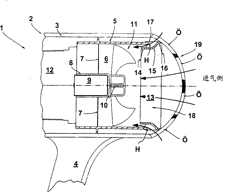
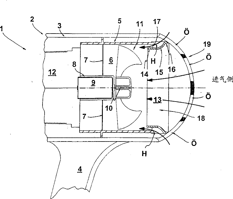
[0037] The following will refer to the attached figure 1 The invention is described with the aid of an exemplary embodiment. figure 1 A partial sectional view in the region of the rear air intake side of the hair dryer 1 as a hot air hair care device is shown. The hair dryer 1 comprises a double-layer housing 2, from which a housing 3 can be seen, on which a handle 4 is integrally formed. Arranged in the double housing 2 of the hair dryer 1 is a tubular annular part 5 , the space enclosed by it forming an airflow channel 6 . The member 5 forming the inner surface of the airflow channel 6 has a cylindrical outer peripheral surface. A motor mount 8 for accommodating an electric motor 9 is formed in the center of the part 5 by means of a partition 7 . Blowing impeller 11 is housed on the transmission shaft 10 of motor 9 . It is designed here that the air supply direction of the blowing impeller 11 is towards the direction of the motor 9 . Therefore, the rear of the hair dryi...


PUM


Abstract

The invention relates to a warm air hair care device, such as a hair blowing device, having a device 1, an air flow channel 6 and a blowing impeller 11; wherein when the device 1 operates, air passes the air flow channel 6; and the blowing impeller 11 is driven by a motor; the air inlet side end zone of the air flow channel 6 has an air inlet and outlet structure which has an axial air inlet 18 and one or more air outlet 17; and the air outlet 17 enables main air flowing direction turn to the radial direction. At least one radial air outlet 17 is required to basically covers the axial air flow of the axial direction.

Description

[0001] The present invention was applied for on January 14th, 2002, and application number is 02101730.1, and title is called the divisional application of hot air hair care device. technical field [0002] The present invention relates to a hot air hair care device, such as a hair drying machine, which has a blowing impeller which is arranged in the airflow channel through which the air flows when the device is in operation and which is driven by an electric motor. In the inlet-side end region of the air flow channel, the air flow channel has an air inlet structure which requires an axial air inlet and one or more air inlets which are diverted from the radial direction to the axial main flow direction. Background technique [0003] In such electric hot air hair care devices such as hair dryers, curling irons or the like, the passage through which the air flows during operation of the device is usually formed as a tubular portion held in the housing of the device. In this tu...

Claims


Application Information

Patent Timeline
Patent Type & Authority Patents(China)
IPC IPC(8): A45D20/12
CPCA45D20/12
Inventor 克劳斯·哈夫曼
Owner WIK FAR EAST
Why Eureka
Try Eureka