
Method for forging thin and short shaft section at end of large-scale step shaft

A step shaft and table stage technology, applied in the field of forging and free forging, can solve the problems of the small weight of the preformed thin and short shaft section a, affecting the size and quality of the forgings, increasing the machining cost, etc., and achieving high raw material utilization and quality. Reliable, easy-to-use forging method results

Inactive Publication Date: 2011-02-23
JIANGSU JINYUAN FORGE
View PDF5 Cites 22 Cited by
  • Summary
  • Abstract
  • Description
  • Claims
  • Application Information

AI Technical Summary

Problems solved by technology

Some step shafts are too thin and short because of the size of the steps at the end. When the material is divided before drawing, the length of the material will be shorter than 1 / 3 of the diameter of the material. In this way, when the thin shaft section of the preform is drawn The concave center seriously affects the size and quality of forgings
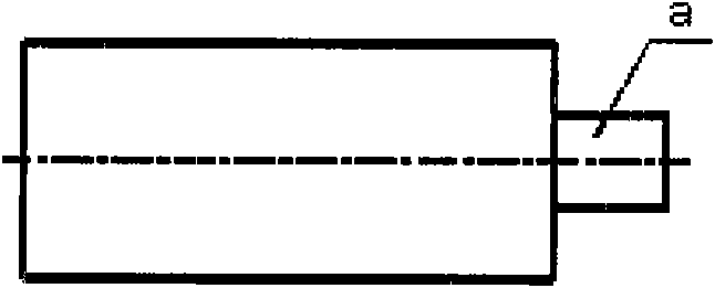
[0003] The general forging method of the existing large-scale stepped shaft with a thin and short shaft section is: first, the steel ingot is upset and drawn to a preform with a diameter greater than D, where D is the diameter of the large stage of the forging after forming, and then, the material is divided and pressed out to form a preform. The short shaft section a of the billet, but because the weight of the short shaft section a of the preform is too small, the parting length is too short, so it cannot be pulled out smoothly
The current solution is to increase the remaining blocks or add process accessories to increase the length of the material, but this causes a great waste of raw materials and increases the cost of machining

Method used


Image

  • Method for forging thin and short shaft section at end of large-scale step shaft
  • Method for forging thin and short shaft section at end of large-scale step shaft
  • Method for forging thin and short shaft section at end of large-scale step shaft

Examples


Embodiment Construction

[0021] In order to make the technical means, creative features, goals and effects achieved by the present invention easy to understand, the present invention will be further described below in conjunction with specific embodiments.

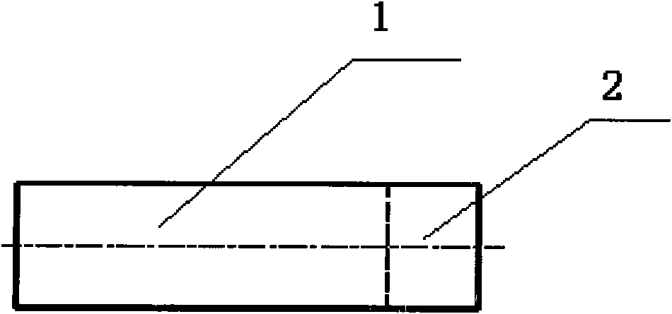
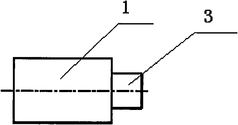
[0022] see figure 2 with image 3 , the forging method provided by the present invention is different from the conventional forging method from large diameter to small diameter, and solves the problem that the thin and short shaft section at the end of a large stepped shaft cannot be formed due to insufficient material distribution, and specifically includes the following steps:

[0023] (A) Forging the preform, the material of the thin and short shaft section 3 of the preform is first separated:

[0024] Assuming that the diameter D of the large platform stage of the forging after forming is φ900, the length is 1200, and the weight is 6000kg, the diameter d of the thin and short shaft section at the end of the forging after forming is φ500, the...


PUM


Abstract

The invention discloses a method for forging a thin and short shaft section at the end of a large-scale step shaft. The method comprises the following steps of: (A) forging a pre-forging part and separating a material for the thin and short shaft section (3) of the pre-forging part; (B), drawing a small step section (2) out to obtain the thin and short section (3) of the pre-forging part; (C) upsetting a large step section (1) in a molding bed; and (D) stripping a mold, and drawing the thin and short shaft section (3) of the pre-forging part and the large step section (1) out to process dimensions so as to forge the thin and short shaft section at the end of the large-scale step shaft. The forging method of the invention is different from a conventional forging method from a large diameter to a small diameter, and solves the problem that the thin and short shaft section at the end of the large-scale step shaft cannot be formed because of the insufficiency of material distribution. A step shaft product produced by the method has continuous forging streamlines, reasonable distribution, stable quality and great reduction of blanking weight of a forge piece. The forging method of the invention is simple and easy to implement, the quality is reliable and the raw material utilization ratio is high.

Description

technical field [0001] The invention relates to a forging method, in particular to a forging method for a thin and short shaft section at the end of a large stepped shaft, which belongs to the technical field of free forging. Background technique [0002] The stepped shaft is a common free forging. The general shape is a large diameter section in the middle and small diameter sections at both ends, such as rotors, rolls, etc.; or a large flange at one end and a small diameter shaft section at the other end, such as wind power spindles and stern shafts. Wait. Some step shafts are too thin and short because of the size of the steps at the end. When the material is divided before drawing, the length of the material will be shorter than 1 / 3 of the diameter of the material. In this way, when the thin shaft section of the preform is drawn The concave center seriously affects the size and quality of forgings. [0003] The general forging method of the existing large-scale stepped...

Claims


Application Information

Patent Timeline
IPC IPC(8): B21J5/06B21K1/06B21J13/02B21J5/08
Inventor 葛艳明李周葛阿金袁志伟杨志华
Owner JIANGSU JINYUAN FORGE
Learn More