Method for manufacturing cushion pad layer of rock protective shed by utilizing waste tyres

A technology for waste tires and buffer cushions, which is applied in protective equipment, construction, etc., can solve problems such as high cost and complex buffer system technology, and achieve strong site adaptability, wide application range of technology, and significant economic and environmental benefits Effect

Inactive Publication Date: 2011-03-02
INST OF GEOLOGY & GEOPHYSICS CHINESE ACAD OF SCI
View PDF5 Cites 22 Cited by
  • Summary
  • Abstract
  • Description
  • Claims
  • Application Information

AI Technical Summary

Benefits of technology

This patented technical solution involves creating an artificially made cover called a roll shield that uses waste rubber materials instead of traditional ones like sand or grit. These covers are designed with specific shapes and dimensions to help reduce rocks from hitting against them during use without causing damage. They provide effective protection while still allowing natural vegetation to grow around their edges over time.

Problems solved by technology

Technological Problem addressed in this patents relates to improving the efficiency and effectiveness of roller bearings used in rubber road safety systems. Current solutions involve adding padding to cover roads with metal shield plugs, making sure they don’t break off when subjected to heavy loads overcomes these drawbacks associated with existing designs. Compact ballistic cushons like cerbrids offer better durability compared to traditional ones, allowing for less maintenance work and reducing damage caused by natural causes. Natural synthetic resin composites provide an alternative solution where various substances can replace conventional building materials without causing negative effects upon environment health concerns.

Method used


Image

  • Method for manufacturing cushion pad layer of rock protective shed by utilizing waste tyres
  • Method for manufacturing cushion pad layer of rock protective shed by utilizing waste tyres
  • Method for manufacturing cushion pad layer of rock protective shed by utilizing waste tyres

Examples


Embodiment Construction

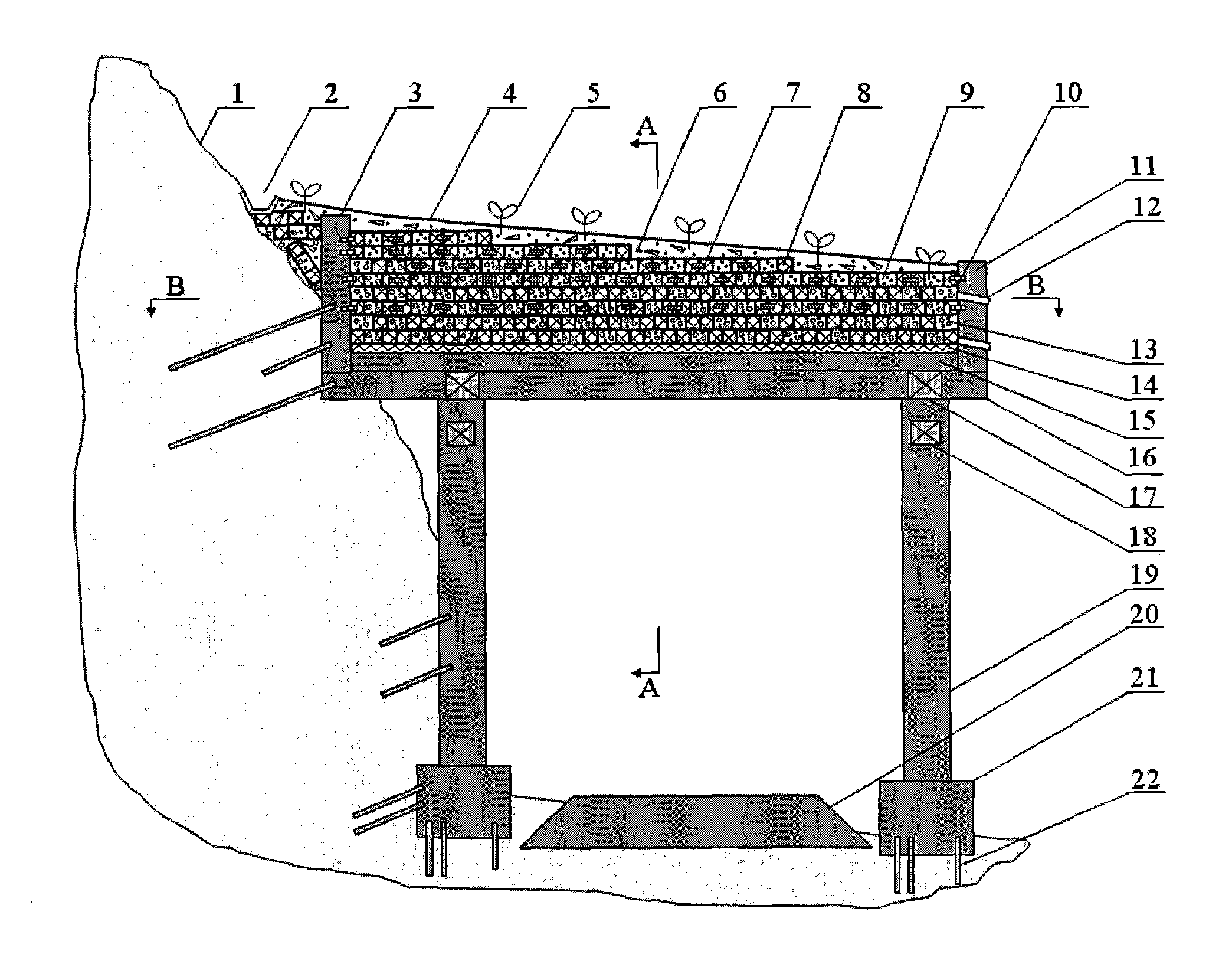
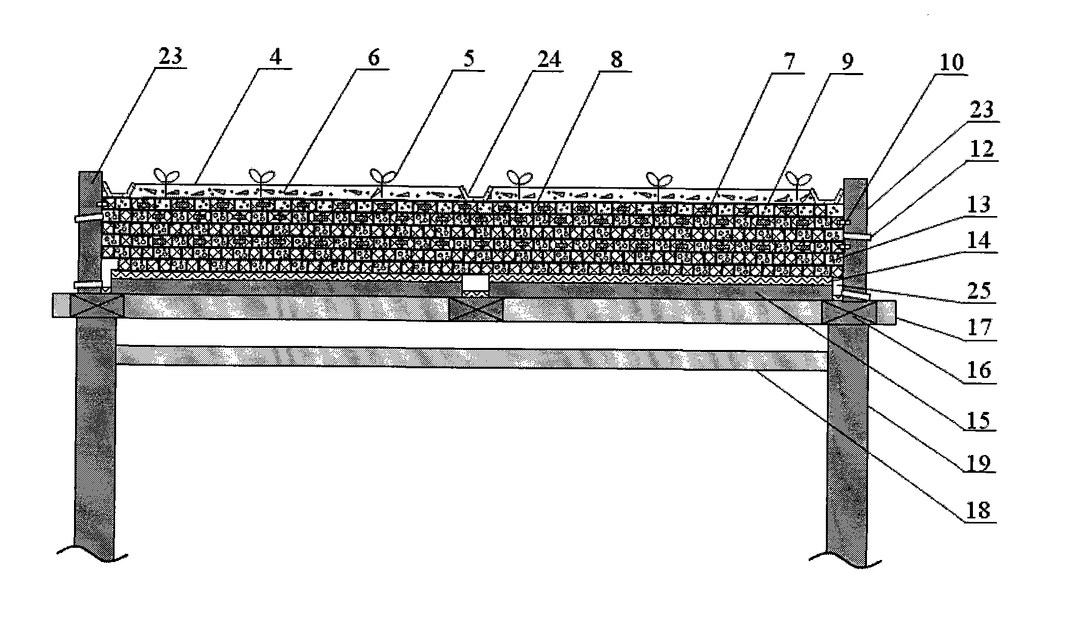
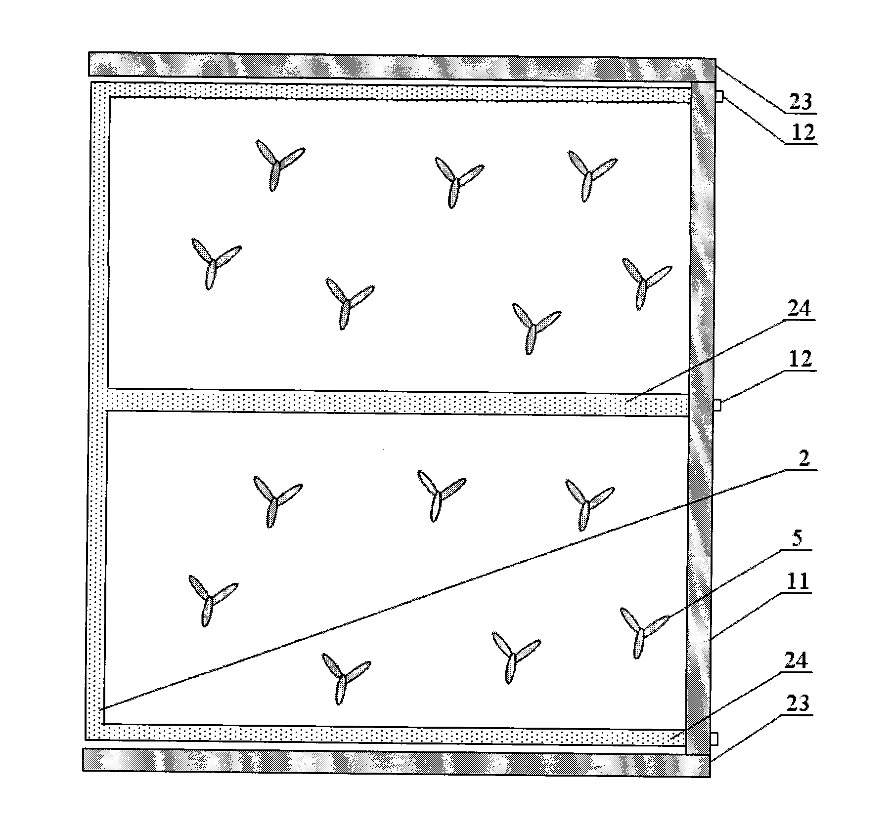
[0064] In order to make the purpose, technical solutions and advantages of the embodiments of the present invention more clear, the embodiments of the present invention will be further described in detail below in conjunction with the embodiments and the accompanying drawings. Here, the exemplary embodiments and descriptions of the present invention are used to explain the present invention, but not to limit the present invention.

[0065] Such as figure 1 and figure 2 As shown, the construction conditions should be determined first, and the construction preparation should be completed; the construction conditions include selecting the specifications and flexibility of the cushion layer, selecting the specifications, arrangement forms, connection methods of waste tires 8 and tire cages 26, and the material ratio of the rubber soil 13 , the type of artificial filling layer 6 and the type of planted plants 5; construction preparation includes site clearing, construction safety...


PUM


Abstract

The invention provides a method for manufacturing a cushion pad layer of a rock protective shed by utilizing waste tyres, comprising the following steps: designing the specifications and flexibility of the cushion pad layer according to the major structure and protection requirements of the rock protective shed and determining the construction conditions; constructing a water-resisting layer, a shed top inner wall, a shed top outer side wall, a shed top end wall, a drainage blind ditch and drain holes on the shed top of the rock protective shed, embedding tyre fixing pieces, and arranging the waste tyres or tyre cages on the shed top in a layered mode; connecting adjacent waste tyres or tyre cages by utilizing tyre connecting pieces at predetermined positions, and utilizing the typre fixing pieces to connect the waste tyres or tyre cages at the boundary of the cushion pad layer respectively with the shed top inner wall, the shed top outer wall and the shed top end wall; filling rubber soil formed by mixing waste rubber particles with sandy soil in a certain proportion into gaps of the waste tyres so that the designed compactness of the cushion pad layer is reached; laying the cushion pad layer until reaching the designed height and gradient, covering an artificial fillstratum formed by mixing macadam and the sandy soil on the surface of the cushion pad layer, and constructing an intercepting ditch and a drainage open trench on the surface of the cushion pad layer; and in terms of the rock protective shed with larger length, constructing the cushion pad layer in a segmental mode, and cultivating plants suitable for growing locally on the surface of the cushion pad layer. The method provided by the invention ensures that the cushion pad layer of the rock protective shed has high-efficiency buffering effect, and the national strategic goal of recycling wastes can be realized by consuming a large quantity of the waste tyres.

Description


Claims


Application Information

Patent Timeline
Owner INST OF GEOLOGY & GEOPHYSICS CHINESE ACAD OF SCI
Why Eureka
Try Eureka