Fire remote visual alarm and remote control fire extinguishing system

A technology of remote control and fire extinguishing system, applied in CCTV systems, alarms, fire rescue and other directions, can solve the problems of missed fire fighting opportunities, delayed remote sharing of fire information, and untimely fire response and handling.

Active Publication Date: 2016-11-30
上饶市广丰区金盾系统科技有限公司
View PDF6 Cites 0 Cited by
  • Summary
  • Abstract
  • Description
  • Claims
  • Application Information

AI Technical Summary

Problems solved by technology

[0002] At present, domestic automatic fire alarm systems are basically based on regional automatic fire alarm systems, centralized fire automatic alarm systems and control center automatic fire alarm systems. These systems are generally self-contained and self-enclosed, and cannot realize remote information between systems. Sharing, it can only respond in the duty room inside the building. When a fire occurs, the system itself cannot automatically report to the city's "119" fire alarm reception center and remotely control the fire extinguishing device to extinguish it, and it cannot reflect the specific fire location and the size of the fire. , resulting in delays in receiving fire alarms, delaying remote sharing of fire information, and missing the best opportunity for firefighting, resulting in inability to save oneself, delayed rescue, and even catastrophe
However, using scientific fire-fighting system equipment to realize fire-fighting remote visual alarm and remote-control fire-extinguishing system technology, thereby improving the accuracy of fire-fighting early warning and monitoring and the ability to respond quickly to disasters has not yet been realized, and the establishment of a unified command and unified management of the city, County and other multi-level fire early warning real-time monitoring and remote emergency command and disaster relief systems are not ideal

Method used


Image

  • Fire remote visual alarm and remote control fire extinguishing system
  • Fire remote visual alarm and remote control fire extinguishing system
  • Fire remote visual alarm and remote control fire extinguishing system

Examples


Embodiment Construction

[0018] Below in conjunction with accompanying drawing, further detailed description will be made to the fire remote visual connection alarm and remote control fire extinguishing system of the present invention.

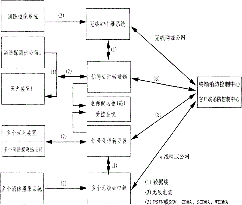
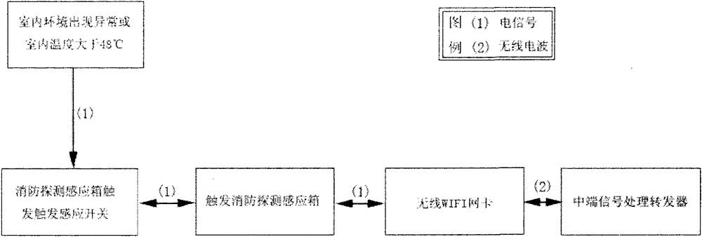
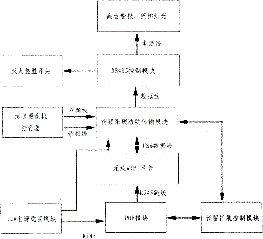
[0019] figure 1The shown fire remote visual alarm and remote control fire extinguishing system is composed of front-end detection and sensing system, mid-end signal processing transponder and terminal remote emergency command platform; front-end detection and sensing system is composed of detection and sensing system and on-site camera system; mid-end The system consists of a signal processing and forwarding system and a relay system. The signal processing and forwarding system consists of an intelligent control host, an intelligent switch, automatic lighting, and a high-pitched siren. The relay system consists of a pair of (superimposed) relay APs, POE power supply modules, Composed of switches; the terminal system consists of alarm center computer, monitor or TV wal...


PUM


Abstract

The invention discloses a fire-fighting remote visual alarm and remote control fire extinguishing system, which is composed of a front-end detection and induction system, a middle-end signal processing transponder and a terminal remote emergency command platform; The temperature sensor and the temperature sensing trigger switch are electrically connected, the fire detection induction box communicates with the intelligent control host of the mid-end signal processing transponder by transmitting wireless signals, and the relay AP of the mid-end signal processing transponder receives and transmits the wireless WIFI network card and the terminal router , network switch connectivity, using the system of the present invention for real-time on-site monitoring and timely feedback, to realize the functions of remote visual reception of police, remote visual control of fire extinguishing, remote dispatch of nearby firefighters for rescue, and remote emergency command rescue and disaster relief at the first time, maximizing Avoid or mitigate losses caused by fire.

Description

technical field [0001] The invention relates to a fire-fighting remote visual alarm and remote control fire extinguishing system, in particular to the remote unified management and remote visual alarm system for the fire protection systems of urban high-rise buildings, super high-rise buildings, underground buildings and large comprehensive buildings. , Remote visual control fire extinguishing and remote emergency command and disaster relief system. Background technique [0002] At present, domestic automatic fire alarm systems are basically based on regional automatic fire alarm systems, centralized fire automatic alarm systems and control center automatic fire alarm systems. These systems are generally self-contained and self-enclosed, and cannot realize remote information between systems. Sharing, it can only respond in the duty room inside the building. When a fire occurs, the system itself cannot automatically report to the city's "119" fire alarm reception center and r...

Claims


Application Information

Patent Timeline
Patent Type & Authority Patents(China)
IPC IPC(8): A62C37/00G08B25/00H04N7/18
Inventor 程良忠余磊余念芝余正生
Owner 上饶市广丰区金盾系统科技有限公司
Why Eureka
Try Eureka