The Structure and Method of Controlling Dam Break Peak Flow

A technology of flood peak flow and dam failure, applied in the structural field of controlling the flood peak flow of dam dam failure, can solve the problems such as the inability to effectively reduce the disaster and safety risks of the dammed lake, the great threat to the safety of construction personnel, and the limited side slope protection, etc. Achieve the effect of delaying the expansion speed of the buffer erosion, fast effect, and delaying the collapse time

Active Publication Date: 2021-11-02
CHINA HYDROELECTRIC ENGINEERING CONSULTING GROUP CHENGDU RESEARCH HYDROELECTRIC INVESTIGATION DESIGN AND INSTITUTE
View PDF0 Cites 0 Cited by
  • Summary
  • Abstract
  • Description
  • Claims
  • Application Information

AI Technical Summary

Problems solved by technology

At present, some people propose to add anti-scouring structures directly in the discharge channel, and some people propose to put artificial structures in the later stage of the discharge of the barrier lake. These two methods have certain problems: the former will cause no erosion in the initial stage of discharge. , the drainage efficiency is low, and the water level of the barrier lake will rise rapidly, which cannot effectively reduce the disaster and safety risks of the barrier lake; the latter is put into an artificial structure in the later stage of water release, and the collapse will develop rapidly at this time, which will pose a threat to the construction workers. The safety threat is huge, and at the same time, a large number of large-scale artificial structures need to be invested in a short period of time to achieve the effect, which is often difficult to achieve, that is, it is not implementable, and the side slope protection is limited

Method used


Image

  • The Structure and Method of Controlling Dam Break Peak Flow
  • The Structure and Method of Controlling Dam Break Peak Flow

Examples


Embodiment Construction

[0019] The invention is further illustrated below in conjunction with the accompanying drawings and specific embodiments.

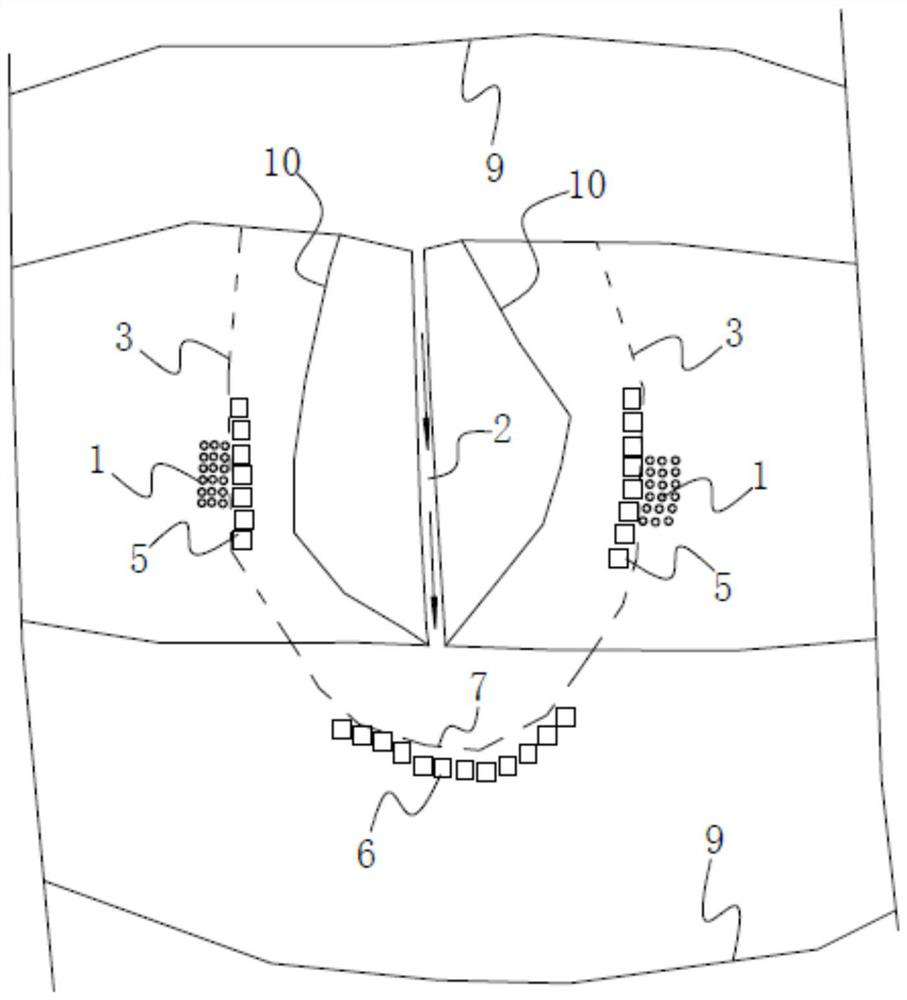
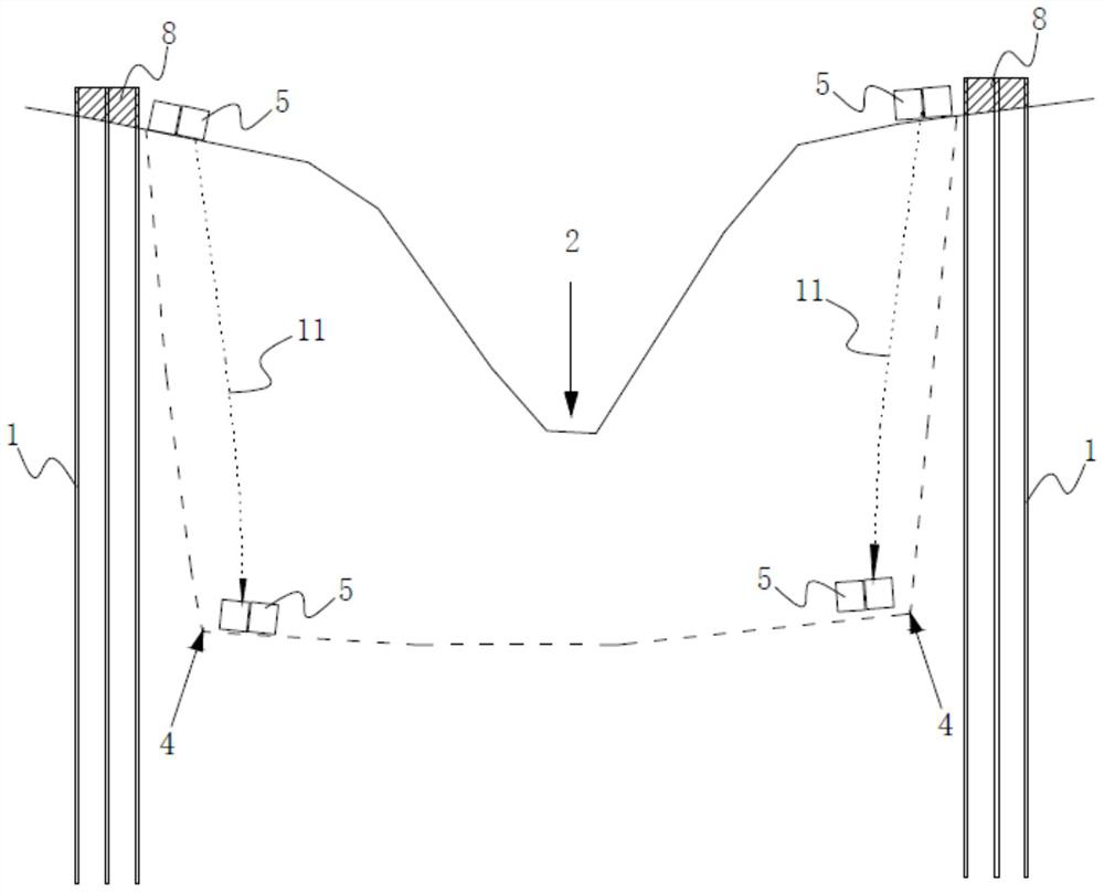
[0020] like Figure 1 to 2 As shown, the present invention controls the barrier dam structure peak flow of the dam, the dam vent plug drains in the lower portion 2 are provided on both sides of the dam with a steel pipe pile 1, and each side of the steel pipe pile 1 are immediately provided in the dam to the outer case 20 in a state in which the corresponding peak flow drains discharge side 2 corresponding to the land-side slope surface of the wire 3, the inner end of the steel pipe pile 1 to a depth of at least 20 to dam in the case of a 4 10m or less in a state corresponding to the peak flow drains discharge side 2 corresponding to the land-side slope foot line.

[0021] 1, in the latter can discharge when drain ditch 2 erosion were gradually expanded to about once every 20 years peak flow state by setting the steel pipe pile, may be disposed in this state b...


PUM


Abstract

The invention discloses a structure and a method for controlling the flood peak flow of a dam break, belonging to the field of disaster prevention and mitigation engineering, and provides a structure and a method capable of effectively controlling the peak flow of a dam break. For the structure of the peak flow of the dam break, steel pipe piles are arranged at the middle and lower parts of the dams on both sides of the discharge channel, and the steel pipe piles on each side are respectively arranged in close proximity to each other in the corresponding state from the dam break to the 20-year flood peak flow state. The outer side of the side bank slope surface line corresponding to the side bank of the discharge channel, the inner end of the steel pipe pile is at least as deep as the side bank corresponding to the side bank of the corresponding discharge channel under the dam break to the 20-year flood peak flow state 10m below the toe line. The invention can delay the expansion speed of erosion on both sides of the discharge channel through the slope protection of steel pipe piles on both sides, the protective cement slurry reinforced gabion on both sides, and the anti-erosion of the outlet impact-resistant cement slurry reinforced gabion, thereby delaying the collapse of the dam time, effectively reduce the maximum flood peak flow of the breach, and achieve the purpose of disaster prevention and mitigation.

Description

Technical field [0001] The present invention relates to a disaster prevention and mitigation, and more particularly, to a structure and method of peak flow control dam barrier dam. Background technique [0002] In recent years, China and the world more active geological structures, heavy rain, strong earthquakes and other extreme disasters-prone, leading to landslides and the formation of lake frequent incidents, is particularly serious in the mountains of southwest China. The past 10 years, a typical occurrence in southwest China landslide blocking the river events and festivals worldwide, such as in 2018 October 11 to November 3, the Jinsha River Brahmaputra and white grid Millington both the territory of the Tibet Autonomous Region spate of four major scale landslides and glacial debris flows were blocked and the Brahmaputra River Jinsha formation of lake. Once the outburst, if not controlled, will have a huge super-standard flood, will Jinsha River in Tibet, Sichuan, Yunnan, ...

Claims


Application Information

Patent Timeline
Patent Type & Authority Patents(China)
IPC IPC(8): E02B7/04E02D27/40
CPCE02B7/04E02D27/40
Inventor 张世殊胡金山冉从彦何顺宾苏星
Owner CHINA HYDROELECTRIC ENGINEERING CONSULTING GROUP CHENGDU RESEARCH HYDROELECTRIC INVESTIGATION DESIGN AND INSTITUTE
Why Eureka
Try Eureka