Central buffering connector

A connector and central technology, applied in the field of central buffer connectors, can solve the problems of unfavorable passenger service life, complex shape, high production and maintenance costs, etc.

Inactive Publication Date: 2011-03-16
CRRC QISHUYAN INSTITUTE CO LTD
View PDF5 Cites 24 Cited by
  • Summary
  • Abstract
  • Description
  • Claims
  • Application Information

AI Technical Summary

Problems solved by technology

[0003] like figure 1 Shown is the structure of the existing central buffer connector. The central buffer connector squeezes the same group of elastic elements when it is subjected to traction and impact. It is known that the assembly of elastic elements has a certain preload, so the preload becomes The initial pressure of the buffer, when the traction or impact force between the vehicles does not exceed the preload of the elastic element, that is, when there is a small traction force and impact force between the vehicles, the buffer connector does not have a buffering effect, and the buffer connector It is a rigid impact, which is not conducive to improving the comfort of passengers and the service life of parts; in addition, it is necessary to make connecting rods, shells and hinges with complex shapes, and the manufacturing and maintenance costs are relatively high

Method used


Image

  • Central buffering connector
  • Central buffering connector
  • Central buffering connector

Examples


Embodiment Construction

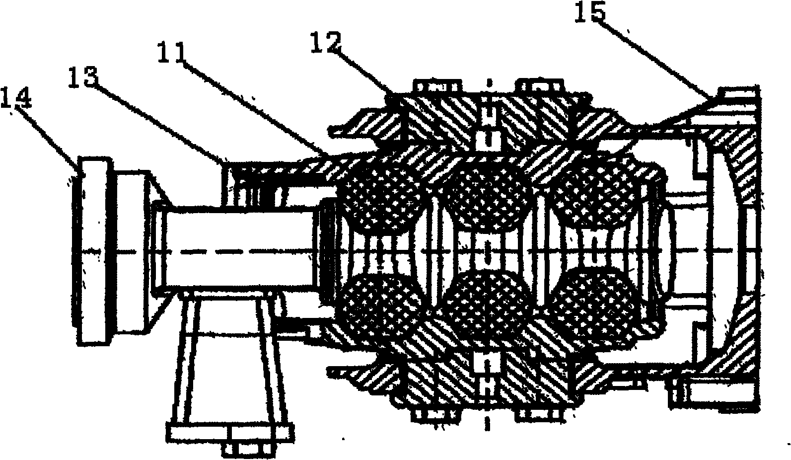
[0017] Such as figure 1 As shown, the central buffer connector of the prior art includes a connecting rod 14, an elastic ring 11, a housing 13, a hinged device 12 and a support seat 15. The housing 13 is composed of upper and lower parts, and the elastic ring 11 is pre-pressed on the housing. In the annular groove formed between the body 13 and the connecting rod 14. The rear end of the connecting rod 14 is connected with the hinge device 12, and is hinged on the connecting plate of the rail vehicle in a horizontally swingable manner through the support seat of the hinge device 12. When the connecting rod 14 is subjected to a normal amount of traction or impact force, the connection rod 14 will move axially relative to the housing 13 , thus shearing the elastic ring 11 to buffer the traction force or impact force. The hinge device 12 undertakes the horizontal swing of the connecting rod 14 on the one hand, and bears the function of impact protection on the other hand. This s...


PUM


Abstract

The invention discloses a central buffering connector. The central buffering connector is applied to railway traffic vehicles, and comprises a connecting shaft, an installation seat, a first elastic element, an intermediate partition plate, a second elastic element, an elastic element pressing plate and a pre-fastening element, wherein the connecting shaft is provided with a front pressure bearing section and a back connecting section; the first elastic element, the intermediate partition plate, the second elastic element and the elastic element pressing plate are sequentially sleeved on the back connecting section of the connecting shaft in a loose fit mode; one side of the first elastic element is pressed against an elastic element stopper on the connecting shaft; the other side of the first elastic element is pressed against one side of the intermediate partition plate; one side of the second elastic element is pressed against the other side of the intermediate partition plate; the other side of the second elastic element is pressed against the elastic element pressing plate; the pre-fastening element is arranged on the end part of the back connecting section and pressed against the elastic element pressing plate; the two ends of the intermediate partition plate are provided with a first rotating shaft and a second rotating shaft respectively; and the first rotating shaft and the second rotating shaft are hinged with the two ends of the installation seat respectively. The central buffering connector can buffer small impact force between vehicles and has a simple structure.

Description

technical field [0001] The invention relates to a buffer device on a rail transit vehicle, in particular to a central buffer connector. Background technique [0002] In rail vehicle technology, a central buffer connector is used to connect two adjacent carriages of a train and form a locked mechanical connection. The connecting shaft of the central buffer connector is designed so that the connector can perform vertical and horizontal swings as well as axial movements, such as occurs when a train runs on a curve. The impact or vibration that occurs during train shunting or braking will cause damage to the vehicle or the connector itself. In order to avoid this damage, it is necessary to limit the transmission of such impact, vibration, etc. The connector is provided with an elastic element for absorbing shock and vibration, and the traction force and impact force which can determine the maximum value are buffered by the elastic element and transmitted to the connecting plate...

Claims


Application Information

Patent Timeline
Patent Type & Authority Applications(China)
IPC IPC(8): B61G9/04
Inventor 杜利清田国明姜晓东杨庆龙邓大伟
Owner CRRC QISHUYAN INSTITUTE CO LTD
Why Eureka
Try Eureka