Cleaning device for looms

A technology for cleaning equipment and looms, used in auxiliary equipment for weaving, textiles, textiles, and papermaking, etc., and can solve problems such as broken yarns and contaminated fabrics

Inactive Publication Date: 2011-03-23
SOHLER NEUENHAUSER
View PDF8 Cites 1 Cited by
  • Summary
  • Abstract
  • Description
  • Claims
  • Application Information

AI Technical Summary

Problems solved by technology

Yarn breaks and soiled fabrics occur in this cleaning equipment

Method used


Image

  • Cleaning device for looms
  • Cleaning device for looms
  • Cleaning device for looms

Examples


Embodiment Construction

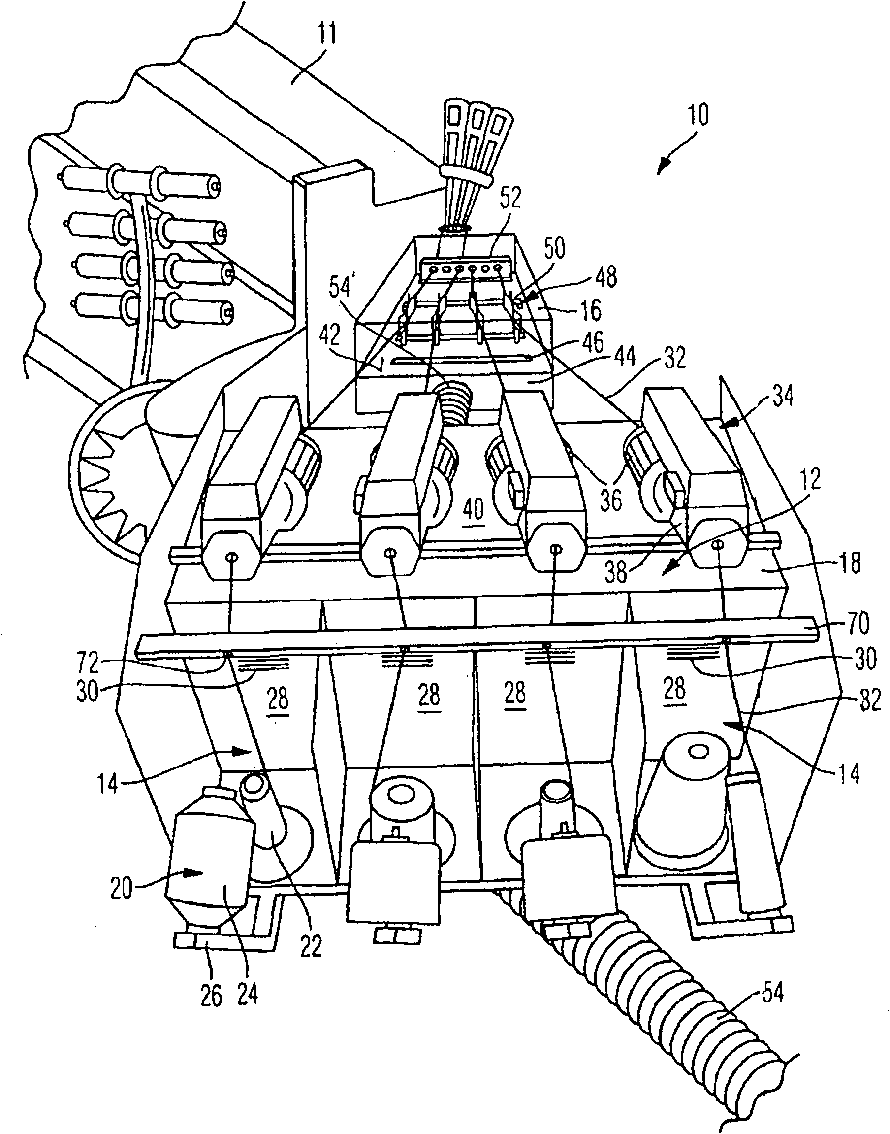
[0028] figure 1A cleaning device 10 according to the invention for a weaving machine 11 is shown, which comprises a discharge or suction device 12 . The discharge or suction device 12 has four open housings 14 which are connected to a common suction connection box 18 . In each housing 14 is accommodated a yarn supply system 20 which each has a first yarn supply reel and a second yarn feed reel, ie a weft reel 22 and a reserve reel 24 . Each housing 14 is designed as an open housing and each has three side walls and a bottom wall on which the weft cylinder 22 is mounted. The storage cylinder 24 is arranged obliquely to the weft cylinder 22 , and the storage cylinder 24 is mounted on a bracket 26 disposed obliquely to the bottom wall of the housing 14 .

[0029] Each of the four housings 14 has a common side wall 28 with the suction connection box 18 , which is provided with a suction opening 30 . The suction openings 30 are formed as slots in the upper part of the side wall ...


PUM


Abstract

The present invention relates to a cleaning device for looms, which comprises at least one discharging or sucking device for fiber fuzz. The discharging or sucking device is provided with at least one sucking opening and is provided in a reversing area of weft. According to the invention, the discharging device (12) is provided with at least one open housing (14,16). The housing is at least partially provided below the weft (32) and / or provided in the reversing area, wherein the housing (14,16) is provided with at least one sucking opening (30) which generates an air flow that comes from at least one housing opening to the sucking opening (30) through the weft (32).

Description

technical field [0001] The invention relates to a cleaning device for a weaving machine according to the preamble of claim 1 . Background technique [0002] Modern textile mills have been increasingly converting to shuttleless weaving machines in recent years and are confronted with changing production conditions here. In a shuttleless weaving machine, the weft thread is withdrawn from a fixedly arranged yarn supply system, which comprises, for example, one or more yarn supply cylinders. With significantly higher running speeds, the weft threads are subjected to increased tension. This leads to significantly increased wear and thus to large dust and fiber fuzz sections. [0003] In this case, the dust and fiber fuzz partly depends on the type of yarn. In particular, more or less intense wear and thus fiber fuzzing occurs with thread-like or fibrous threads. This problem is particularly acute at locations where the yarn is subjected to frictional or abrasive stresses, suc...

Claims


Application Information

Patent Timeline
Patent Type & Authority Applications(China)
IPC IPC(8): D03J1/02
CPCD03J1/002
Inventor M・佐勒
Owner SOHLER NEUENHAUSER
Why Eureka
Try Eureka