Ultrasonic sensing device with function of adjusting signal attenuation time and application method

A technology of time adjustment and signal attenuation, applied in measuring devices, radio wave measuring systems, using re-radiation, etc., can solve the problem of inability to clearly distinguish reflected wave waveforms, inability of ultrasonic sensing devices to detect at close range, long attenuation time, etc. question

Inactive Publication Date: 2011-03-23
LITE ON IT
View PDF0 Cites 8 Cited by
  • Summary
  • Abstract
  • Description
  • Claims
  • Application Information

AI Technical Summary

Problems solved by technology

Although the attenuation signal RS reaches a state smaller than the trigger boundary L at time t1, the required attenuation time is too long, which means that the dead zone Z d The range of the reflection signal ES is too large, but it fails to reach the state smaller than the trigger boundary L before the time t2 when the reflection signal ES is received, which in turn affects the reception of the subsequent reflection signal ES and results in the mixing of the two signals, making the processing impossible. Clearly distinguish the time of receiving the reflected wave and its corresponding waveform
Therefore, the dead zone Z d The existence of the ultrasonic sensor will cause the ultrasonic sensing device to be unable to perform short-distance detection

Method used


Image

  • Ultrasonic sensing device with function of adjusting signal attenuation time and application method
  • Ultrasonic sensing device with function of adjusting signal attenuation time and application method
  • Ultrasonic sensing device with function of adjusting signal attenuation time and application method

Examples


Embodiment Construction

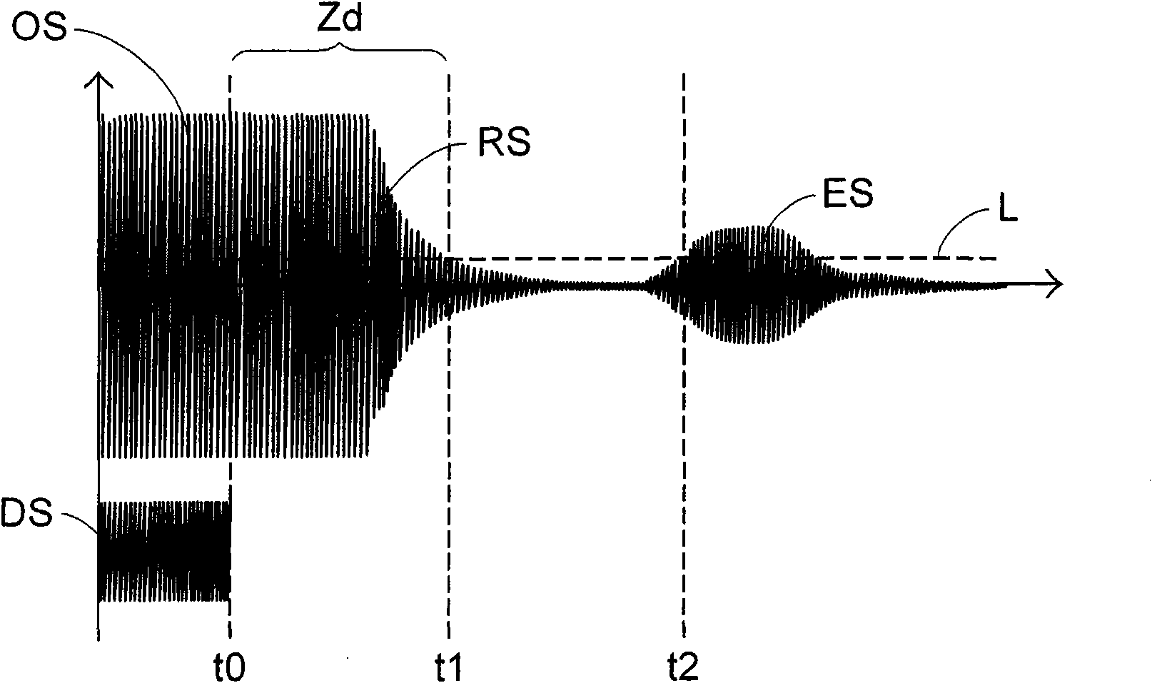
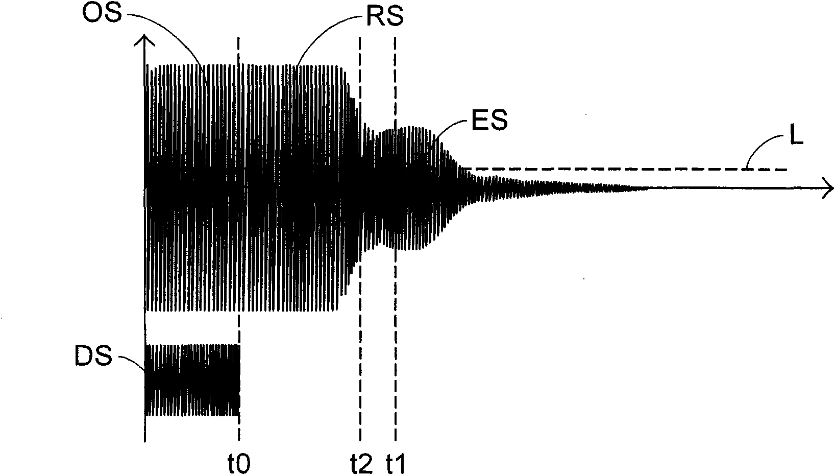
[0033] As described in the prior art, when the ultrasonic sensing device applies a driving voltage to the piezoelectric sheet to generate vibrations and emit ultrasonic waves, and the driving signal stops operating, a so-called dead zone (Dead Zone) appears on the waveform. ) attenuation signal, it may affect the reception and processing of subsequent reflected signals. Because the degree of this influence will vary depending on the time length of the dead zone on the waveform distribution of the signal presented over time, for example, the larger the range of the dead zone, the greater the range of objects that the ultrasonic sensing device cannot measure. . If the time length of the dead zone is 0, it means that the object can also be detected when it is close to the surface of the ultrasonic sensing device. In other words, when the range of the dead zone in the waveform distribution presented by the signal over time is larger, the degree of influence will increase; therefo...


PUM


Abstract

The invention relates to an ultrasonic sensing device with the function of adjusting signal attenuation time and an application method, the device comprises a pre-processing module and an ultrasonic transceiving module, and the method comprises the following steps: leading the pre-processing module to produce a first driving signal so as to lead the ultrasonic transceiving module to receive the first driving signal, provide vibration according to the first driving signal and transmit a sensing wave; leading the pre-processing module to stop the first driving signal so as to lead the vibration in the ultrasonic transceiving module to enter into the attenuation state and further form an attenuation signal; leading the pre-processing module to produce a second driving signal according to the first driving signal and transmit the second driving signal onto the ultrasonic transceiving module; and leading the ultrasonic transceiving module to receive the second driving signal and offset the attenuation signal trough the second driving signal so as to shorten the attenuation time of the attenuation signal and further receive a reflected wave after reflecting the sensing wave.

Description

technical field [0001] The invention is an ultrasonic sensing device with signal decay time adjustment function and a method applied thereon. In particular, it refers to a device and method for rapidly reducing vibration by inputting a drive signal with a specified phase, amplitude, pulse number and frequency to the component that generates ultrasonic waves to reduce the decay time of the internal decay signal. Background technique [0002] Ultrasonic Transducer is a widely used device utilizing ultrasonic transmission technology. In the current application, the ultrasonic sensing device can be a single emission type, that is, to generate the desired vibration effect by emitting sound waves of a specific frequency; or it can also be a design that includes both ultrasonic emission and reception of its reflection, That is to say, both the transmitter and the receiver are arranged in the ultrasonic sensing device, and both of them face the same direction to transmit the ultras...

Claims


Application Information

Patent Timeline
Patent Type & Authority Applications(China)
IPC IPC(8): G01S7/521G01S15/08
CPCG01S7/527G01S7/524
Inventor 陈翰霆廖显庆斯蒂夫·范贝克霍芬乔翰·卡夫斯米歇尔克兰·史沃明
Owner LITE ON IT
Why Eureka
Try Eureka