
Radiation detector assembly

A radiation detection and radiation detector technology, applied in the field of radiation, can solve problems such as difficult operation, difficult use due to deliquescence, and not being used as a scintillation object

Inactive Publication Date: 2007-02-07
JAPAN SCI & TECH CORP
View PDF2 Cites 9 Cited by
  • Summary
  • Abstract
  • Description
  • Claims
  • Application Information

AI Technical Summary

Problems solved by technology

[0004] Among practical scintillators, only barium fluoride (BaF 2 ) has a unique sub-nanosecond decay time constant (600 picoseconds) (non-patent document 1), but the wavelength of its fast fluorescent component is 225nm, which is very short, and it is necessary to use an expensive ultraviolet detector, etc., and its operation very difficult
[0005] On the other hand, BaCl 2 In other words, the fluorescence lifetime after X-ray irradiation is measured (Non-Patent Document 2), but since a material with high speed and a large amount of light emission is required in the field of radiation measurement, and it is difficult to use due to the presence of deliquescence in this material, it is basically not regarded as scintillation. research

Method used


Image

  • Radiation detector assembly
  • Radiation detector assembly
  • Radiation detector assembly

Examples


manufacture example 1

[0032] According to the following procedure to prepare barium chloride (BaCl 2 ) crystals.

[0033] In a carbon crucible with an inner diameter of 60 mm, add 850 g of BaCl 2 (manufactured by Aldrich, purity 99.999%, composition ratio Ba:Cl=1:2, cubic crystal structure, specific gravity 3.096, refractive index 1.646), and placed in a furnace. The inside of the furnace was made into a vacuum state (vacuum degree: ~10-5 Pa) using a rotary pump and an oil diffusion pump. This was heated by a heater and dried at a low temperature (120° C., 24 hours).

[0034] According to the temperature raising program, the furnace was heated to 970° C. and kept for 24 hours. The crucible was pulled down 105 mm at a pulling speed of 0.3 mm / h (about 350 hours). After cooling to room temperature (96 hours) and slowly cooling, take it out, and carry out molding and grinding.

[0035] Using silicone grease, the BaCl thus obtained 2 The crystal was directly attached to the light-receiving surface o...

Embodiment 1

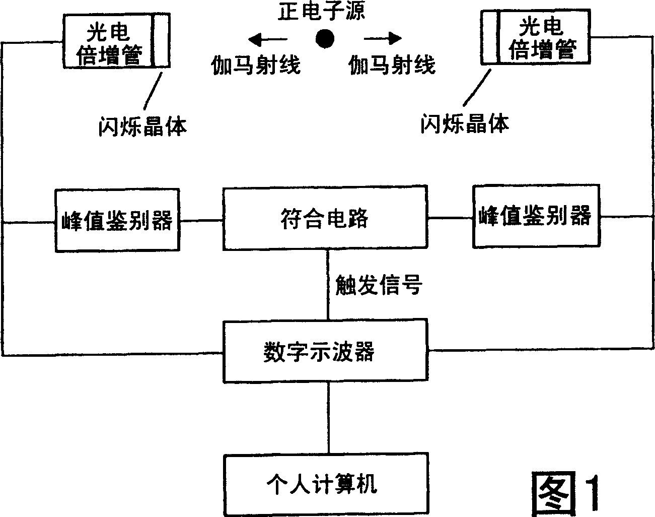
[0039] In the measuring system shown in Fig. 1, barium chloride (BaCl 2 ) crystal, and in another, a barium fluoride crystal was used.

[0040] Using 68Ge as a radiation source, time difference measurement of positron annihilation gamma rays (0.511 MeV) was performed. Make two output branches from the photomultiplier tube, one is directly input to a high-speed digital oscilloscope (LeCroy WavePro 7100), and the other is input to a peak discriminator and a coincidence circuit, and a trigger is applied to the oscilloscope. Input the measurement data into the microcomputer for analysis.

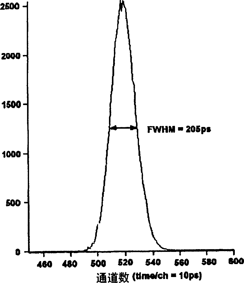
[0041] figure 2 The results of time-difference measurements of positron annihilation gamma rays performed by the present device are shown in . According to this figure, the time resolution capability (full width half width of the curve) of the time difference measurement is 205ps.

Embodiment 2

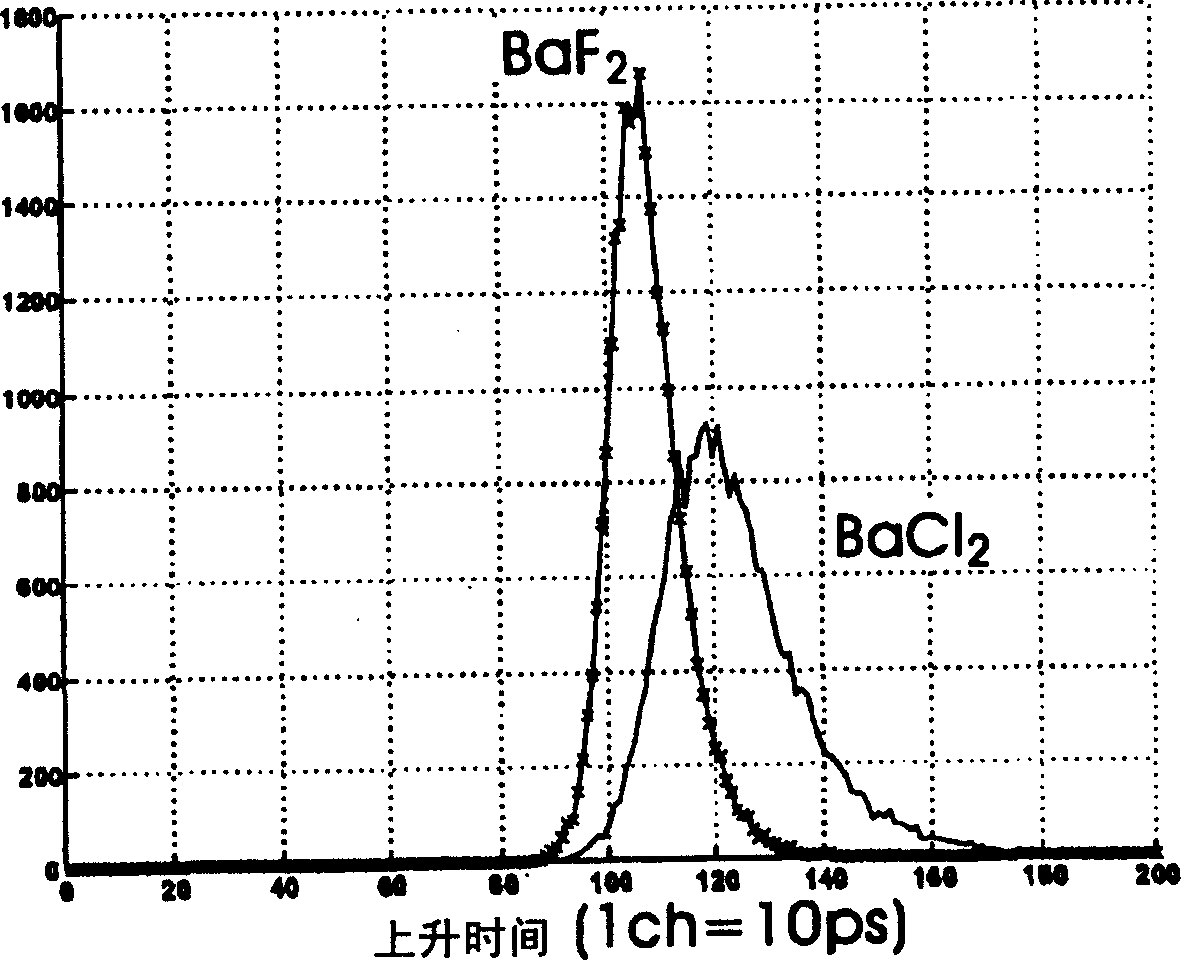
[0043] Next, according to the measurement result of embodiment 1, compare BaCl 2 Scintillation and BaF 2 The rise time of the measured waveform of the scintillation object. The result is used image 3 express.

[0044] It can be seen that for BaF 2 , distributed between 900~1300ps, for BaCl 2 with BaF 2 Compared with some delays, the distribution is between 1000 ~ 1600ps. Thus, it can be seen that BaCl 2 is close to BaF 2 Time-response properties of scintillation crystals.


PUM


Abstract

The invention provides a scintillation crystal containing a fluorescent component with excellent luminous efficiency and short decay time while the wavelength of the emitted light being in the visible light region or very near the visible light region and a radiation detection device using the scintillation crystal having an excellent timing resolution capability. Barium chloride (BaCl 2 ) is used as the scintillation crystal. A radiation detection device comprising a barium chloride crystal as a scintillator and a photomultiplier tube to receive the light from the scintillator wherein the wavelength of the light emitted from the scintillator is between 250 nm and 350 nm and the scintillator is located in a low humidity atmosphere.

Description

technical field [0001] The invention relates to a detection device for radiation, especially gamma rays. In more detail, the present invention relates to a gamma ray detection device with a very fast timing resolution capability. Background technique [0002] In the existing gamma ray detectors, especially in the lifetime measurement (Positron Annihilation Lifetime; PAL) of the positron annihilation gamma ray (0.511 MeV), it cannot be said that a sufficient time resolution capability can always be obtained so far. In practical applications, time resolution is very important. For example, by improving the time resolution capability of PET (Positron Emission Tomography: Positron Emission Tomography) in medicine, the position detection accuracy of positrons can be improved based on time information. As a result, the measurement time can be shortened and the radiation source intensity can be reduced. Reduce the burden on the person being tested. Also, in materials science, si...

Claims


Application Information

Patent Timeline
Patent Type & Authority Applications(China)
IPC IPC(8): G01T1/20G01T1/202C09K11/00C09K11/61
CPCG01T1/2023G01T1/20C09K11/61G01T1/202
Inventor 村上英利渋谷宪悟斋藤晴雄浅井圭介本多庸郎
Owner JAPAN SCI & TECH CORP
Learn More