

Anti-fatigue sole
An anti-fatigue and heel technology, applied in soles, footwear, applications, etc., can solve problems such as walking resistance and fatigue, and achieve the effect of eliminating walking resistance.
Inactive Publication Date: 2011-03-30
王春龙
View PDF0 Cites 0 Cited by
- Summary
- Abstract
- Description
- Claims
- Application Information
AI Technical Summary
Problems solved by technology
In order to solve this technical problem, in the prior art, the shape of the sole is usually designed to be more in line with the physiological structure of the human foot, so as to bring people better comfort, but because the material of the sole is still made of rubber or Plastic, so in the process of walking, the sole will rub against the ground to generate static electricity, which will cause walking resistance, and this is also the main cause of fatigue caused by long-term walking
Method used
View moreImage
Smart ImageViewing Examples


Examples
Embodiment 1
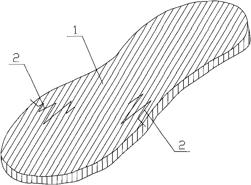
[0016] Such as figure 1 As shown, a kind of anti-fatigue shoe sole comprises a body 1, and is characterized in that: a conductor 2 is arranged in the body 1, and one end of the conductor 2 protrudes from the body 1; the conductor 2 is a metal wire; The part where the conductor 2 is located in the body 1 is wavy; the conductor 2 is located at the part of the sole corresponding to the sole; two conductors 2 are arranged in the body 1; the conductor 2 is located in the body 1 inner interval setting.
Embodiment 2
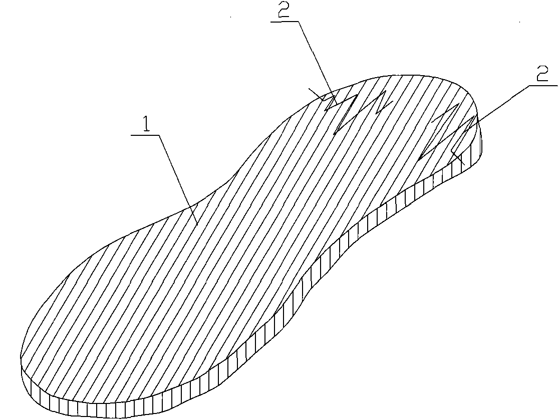
[0018] Such as figure 2 As shown, the difference between this embodiment and Embodiment 1 is that the conductor 2 is located at the heel. Other structures of this embodiment are the same as those of Embodiment 1.
Login to View More PUM
 Abstract
The invention provides an anti-fatigue sole. The anti-fatigue sole comprises a body (1), and is characterized in that a conductor (2) is arranged in the body (1), wherein one end of the conductor (2) is extended out of the body (1). The anti-fatigue sole can effectively reduce walking resistance, so that the anti-fatigue sole is comfortable and has good ant-fatigue effect.
Description
technical field [0001] The invention relates to an anti-fatigue shoe sole. Background technique [0002] In order to make the shoes more comfortable to wear, rubber or plastics are generally used as the material of the sole, but even so, if people walk for a long time, they will still feel certain fatigue. In order to solve this technical problem, in the prior art, the shape of the sole is usually designed to be more in line with the physiological structure of the human foot, so as to bring people better comfort, but because the material of the sole is still made of rubber or Plastic, so in the process of walking, the sole will rub against the ground to generate static electricity, which will cause walking resistance, and this is also the main cause of fatigue caused by long-term walking. Contents of the invention [0003] The object of the present invention is to provide a kind of sole that can eliminate walking static electricity so as to resist fatigue. [0004] The o...
Claims
Login to View More Application Information
Patent Timeline
 IPC IPC(8): A43B13/00
Inventor王春龙
Owner王春龙