Tool with bent angle

An angle and bending technology, which is applied in the field of tools with bending angles, can solve the problems that the cable cannot provide enough torque, the locking force of the screw cannot meet the expectation, and is not applicable.

Inactive Publication Date: 2011-03-30
陈财庆
View PDF3 Cites 3 Cited by
  • Summary
  • Abstract
  • Description
  • Claims
  • Application Information

AI Technical Summary

Problems solved by technology

The cable can provide bending effect because of its spoolability, but also because of the spoolability feature, the cable cannot provide enough torque, so that the locking force of the screw cannot reach the expected goal, so this kind of cable Type joints can only be used in lightweight designs, and are not suitable for machines that require a standard locking force

Method used


Image

  • Tool with bent angle
  • Tool with bent angle
  • Tool with bent angle

Examples


Embodiment Construction

[0069] In order to make the object, technical solution and advantages of the present invention clearer, the implementation manner of the present invention will be further described in detail below in conjunction with the accompanying drawings.

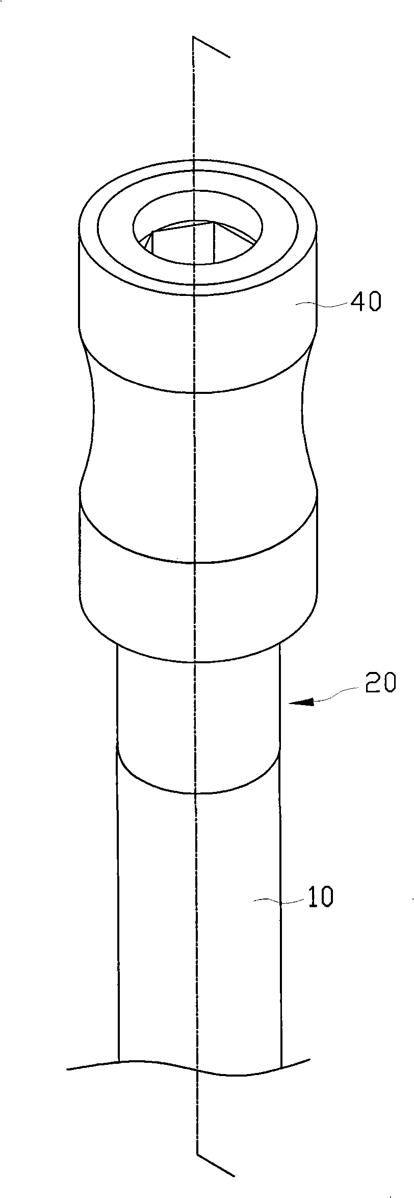
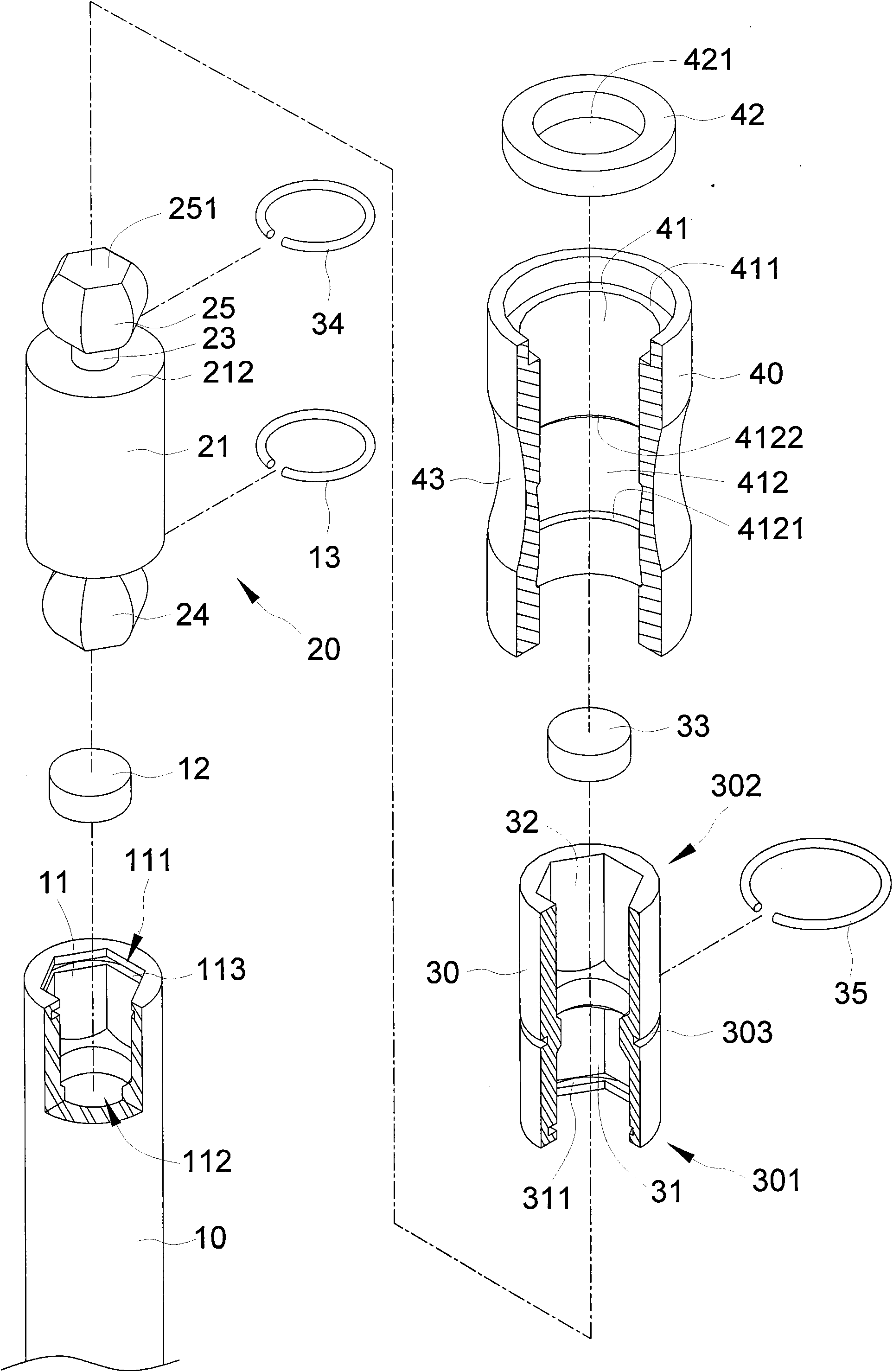
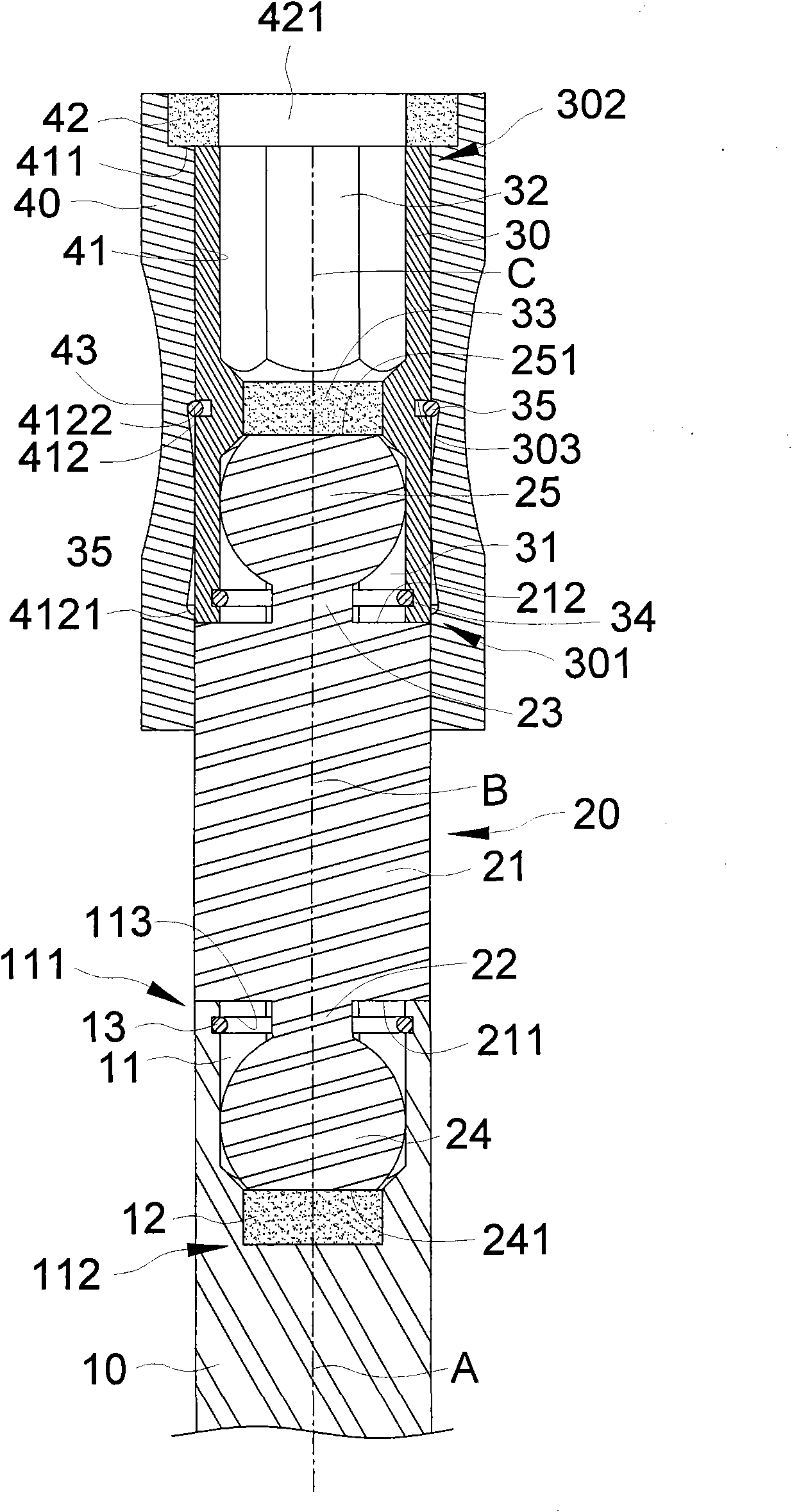
[0070] refer to figure 1 , figure 2 and image 3 , is a three-dimensional appearance view, three-dimensional exploded view and a schematic cross-sectional view of the tool with a bending angle provided by the first embodiment of the present invention. The tool with a bending angle provided by the first embodiment of the present invention includes a rod 10 , a double-end joint 20 , a receiving member 30 and a sliding sleeve 40 .

[0071] The rod 10 includes a first coupling portion 11 , a positioning component 12 and a blocking component 13 . An end of the bar 10 opposite to the first coupling portion 11 can be connected with a handle or a power tool. One end of the first joint portion 11 is an open end 111 , and the other end is ...


PUM


Abstract

The invention discloses a tool with a bent angle, and belongs to the field of machinery. The tool comprises a rod piece, a double-head joint and an adapting piece, which are provided with a virtual axis respectively; the double-head joint can be pivoted between a first position and a second position relative to the rod piece; when the double-head joint is positioned at the first position, the first axis is collinear with the second axis; when the double-head joint is positioned at the second position, the first axis and the second axis form a first bent angle; the adapting piece is pivoted between the first position and the second position relative to the double-head joint; when the adapting piece is positioned at the first position, the second axis is collinear with the third axis; and when both the double-head joint and the adapting piece are positioned at the second position, the first axis and the third axis form a second bent angle.

Description

technical field [0001] The invention relates to the mechanical field, in particular to a tool with a bending angle. Background technique [0002] The post-type hand tool has multiple uses because it can accept different styles of screwdriver bits. [0003] refer to Figure 10 , a common screwdriver chuck provided in the prior art, which includes a set and a rod, the set is set on the rod, the rod is provided with a socket hole, the socket hole can be socketed with a screwdriver head, and one end of the set is provided A magnetic body, the other end of the kit slides a rod so that the rod can slide in the kit. Since the rod moves between the first position and the second position, the screwdriver head can be quickly disassembled. [0004] The above-mentioned screwdriver chuck is used in such a way that the screwdriver chuck is sleeved on the screwdriver head, and the screwdriver head is used to drive the screw or the object to be driven. The central axis of the screwdriver h...

Claims


Application Information

Patent Timeline
IPC IPC(8): B25G1/06
Inventor 陈财庆
Owner 陈财庆
Why Eureka
Try Eureka