Metal pipe bending machining device based on measuring assembly

A technology for bending processing and measuring components, applied in metal processing equipment, feeding devices, positioning devices, etc. Efficiency reduction and other problems, to achieve the effect of simple structure, increasing the scope of application, and improving the scope of application

Active Publication Date: 2020-12-18
安徽鳌鸟信息科技有限公司
View PDF7 Cites 1 Cited by
  • Summary
  • Abstract
  • Description
  • Claims
  • Application Information

AI Technical Summary

Problems solved by technology

[0004] The object of the present invention is to provide a metal pipe bending processing device based on a measuring assembly, which is driven by a push block, an internal thread block, a first electromagnet, a second electromagnet, a first arc splint, a second arc splint, and bending The design of the plate, linear scale line, angle measuring disc, hydraulic rod and transmission belt solves the problem that the existing metal tube bending equipment cannot simultaneously bend multiple metal tubes, resulting in a greatly reduced efficiency of metal tube bending and a greatly increased The labor intensity of the operator cannot meet the clamping and bending of metal pipes with different diameters, resulting in a small range of application of metal pipe bending equipment, which is not convenient for linear measurement of bending processing of metal pipes at different positions, and is not convenient for the bending angle of metal pipes measurement problem

Method used


Image

  • Metal pipe bending machining device based on measuring assembly
  • Metal pipe bending machining device based on measuring assembly
  • Metal pipe bending machining device based on measuring assembly

Examples


Embodiment Construction

[0043]The following will clearly and completely describe the technical solutions in the embodiments of the present invention with reference to the accompanying drawings in the embodiments of the present invention. Obviously, the described embodiments are only some, not all, embodiments of the present invention. Based on the embodiments of the present invention, all other embodiments obtained by persons of ordinary skill in the art without creative efforts fall within the protection scope of the present invention.

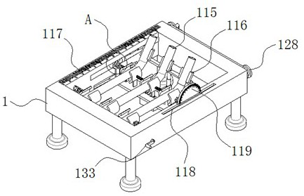
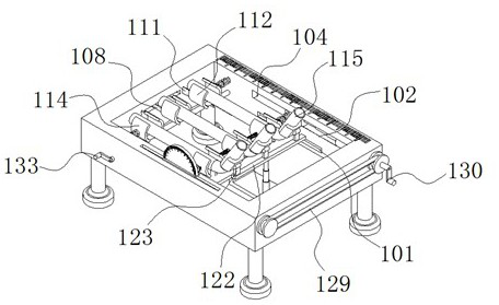
[0044] see Figure 1-9 , the present invention is a metal pipe bending processing device based on measuring components, including a mounting table 1;

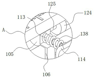
[0045] The installation platform 1 is provided with a first chute 101 and an installation groove 102 on the opposite inner sides; the inside of the first chute 101 is fixedly connected with a support plate 103 through a slider;

[0046] The interior of the installation groove 102 is provided with a threaded groove 1...


PUM


Abstract

The invention discloses a metal pipe bending machining device based on a measuring assembly, and relates to the technical field of metal pipe bending devices. The device comprises a mounting table; one end of one of first supporting rods is fixedly connected with a first electromagnet; one end of the other first supporting rod is fixedly connected with a second electromagnet; one end of a second supporting rod is fixedly connected with a first arc-shaped clamping plate; one end of a first telescopic part is fixedly connected with a second arc-shaped clamping plate; a bending driving plate is attached to the outer wall of a metal pipe; the upper surface of the mounting table is fixedly connected with linear scale lines; and an angle measuring disc is fixedly connected into a second slidinggroove through a sliding block. Through the design of a sliding clamping groove, the first electromagnet, the second electromagnet, the second supporting rod, the first arc-shaped clamping plate, thefirst telescopic part, the second arc-shaped clamping plate, a fourth telescopic part, a first spring and a two-way threaded rod, stable clamping of metal pipes with different pipe diameters can be achieved, and the application range of the metal pipe bending device is greatly widened.

Description

technical field [0001] The invention belongs to the technical field of metal pipe bending devices, in particular to a metal pipe bending processing device based on a measuring component. Background technique [0002] Metal pipe fittings are bent into shape by determining a reasonable fulcrum and stress point and applying a certain bending moment or bending force. At present, metal pipes are widely used as pipes for transporting fluids such as oil, gas and various liquids in industrial facilities such as complete sets of equipment, factories and power plants, or as skeleton structural materials of buildings such as bridges and stadium roofs. application. These metal pipes are widely used due to the use of standardized pre-manufactured pipes in a predetermined shape, and on the other hand, because the pipes that are bent by the construction object can flexibly correspond to various curvatures and pipe shapes. application. [0003] When metal pipe bends are used in different...

Claims


Application Information

Patent Timeline
Patent Type & Authority Applications(China)
IPC IPC(8): B21D7/16B21D7/14B21D43/00
CPCB21D7/14B21D7/16B21D43/003B21D43/006
Inventor 梁爱华
Owner 安徽鳌鸟信息科技有限公司
Why Eureka
Try Eureka