
Three-dimensional code positioning and scanning device

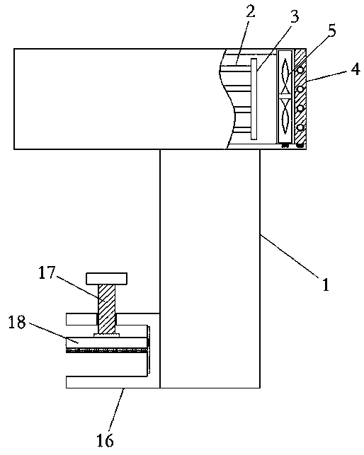
A technology for positioning scanning and scanning equipment, which is applied in the field of three-dimensional codes. It can solve the problems that the fixed rods cannot be connected together, the scanning equipment is inconvenient for positioning and scanning, and the heat affects the normal operation of the scanning equipment. It is easy to disassemble, improve heat dissipation efficiency, and facilitate The effect of using

Inactive Publication Date: 2019-05-21
河南智慧中原科技发展有限公司
View PDF0 Cites 0 Cited by
  • Summary
  • Abstract
  • Description
  • Claims
  • Application Information

AI Technical Summary

Problems solved by technology

[0004] The purpose of the present invention is to solve the problem that the internal electronic parts of the three-dimensional code scanning equipment in the prior art will generate a lot of heat after a long time of use, which will affect the normal operation of the scanning equipment, and the current scanning equipment cannot be easily integrated with the scanning equipment. The fixed rods are relatively connected together, and it is inconvenient to use the scanning device for positioning scanning, and a three-dimensional code positioning scanning device is proposed

Method used


Image

  • Three-dimensional code positioning and scanning device
  • Three-dimensional code positioning and scanning device

Examples


Embodiment Construction

[0019] The following will clearly and completely describe the technical solutions in the embodiments of the present invention with reference to the accompanying drawings in the embodiments of the present invention. Obviously, the described embodiments are only some, not all, embodiments of the present invention.

[0020] In describing the present invention, it should be understood that the terms "upper", "lower", "front", "rear", "left", "right", "top", "bottom", "inner", " The orientation or positional relationship indicated by "outside", etc. is based on the orientation or positional relationship shown in the drawings, and is only for the convenience of describing the present invention and simplifying the description, rather than indicating or implying that the referred device or element must have a specific orientation, so as to Specific orientation configurations and operations, therefore, are not to be construed as limitations on the invention.

[0021] refer to Figure ...


PUM


Abstract

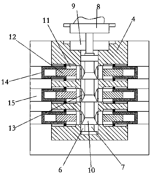
The invention discloses a three-dimensional code positioning and scanning device. The device comprises a scanning device body. A plurality of heat conducting rods which are in contact connection withthe control circuit board are uniformly and fixedly connected to the position, corresponding to the control circuit board, in the scanning device body. The ends, away from the control circuit board, of the heat conduction rods are fixedly connected with the same heat dissipation plate, the side wall of the scanning device body is provided with an opening corresponding to the heat dissipation plate, the upper end of the scanning device body is provided with a bayonet, a positioning plate is clamped in the bayonet, and the side, close to the heat dissipation plate, of the positioning plate is fixedly connected with a heat dissipation fan. According to the invention, the heat dissipation efficiency of the scanning device body is greatly improved.

Description

technical field [0001] The invention relates to the technical field of three-dimensional codes, in particular to a three-dimensional code positioning scanning device. Background technique [0002] With the development of society, because the two-dimensional code is a passive identification technology, it lacks creative design. Whether it is a one-dimensional barcode or a two-dimensional code, it is printed on a plane and is a two-dimensional space code. These codes use bars and spaces of a certain length and width to represent data, and four bars and four spaces represent one. byte. Compared with the one-dimensional code, the two-dimensional code has the advantage of large amount of information because it has more one-dimensional data. The three-dimensional code adds another dimension on the basis of the two-dimensional code, and it can represent more data and have more information capacity. That is, any point in the space can be described by the parameters of the X-axis,...

Claims


Application Information

Patent Timeline
Patent Type & Authority Applications(China)
IPC IPC(8): G06K7/10
Inventor 李明施皓然施雯月施静修
Owner 河南智慧中原科技发展有限公司
Learn More