aircraft arm

An aircraft and arm technology, applied in the field of aircraft arms, can solve the problems of large arm span and easy breakage, and achieve the effects of improving stability, simple structure and improving operation safety.

Active Publication Date: 2021-11-16
POWERVISION ROBOT INC
View PDF5 Cites 0 Cited by
  • Summary
  • Abstract
  • Description
  • Claims
  • Application Information

AI Technical Summary

Problems solved by technology

[0004] However, in the existing aircraft, the stretched arms and tripods are all fixedly connected to the fuselage. After use, the large arm span makes the aircraft have higher requirements for storage space. The weight of the aircraft itself needs to be considered, and the structure of each part of the aircraft is relatively simple. Therefore, the large arm span also leads to the danger of easy damage caused by improper storage

Method used


Image

  • aircraft arm
  • aircraft arm
  • aircraft arm

Examples


Embodiment 1

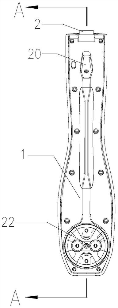
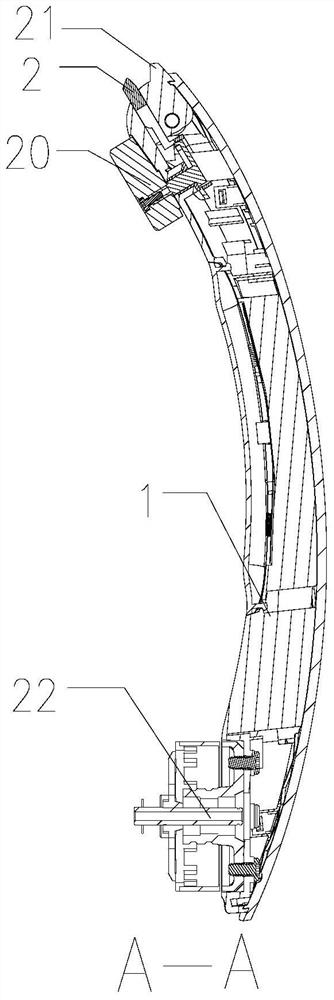
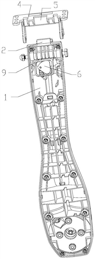
[0034] Such as Figure 1 to Figure 5 As shown, an aircraft arm of the present invention comprises an arm mount 4 fixed on the main body of the aircraft, an aircraft arm 1 that is rotatably connected to the arm mount 4, and an aircraft arm 1 and an arm that are arranged on the aircraft arm. The locking mechanism between the mounting bases 4, the locking mechanism includes a limiting part arranged at the end of the rotating shaft of the aircraft arm 1, which is arranged on the arm mounting base 4 and extends toward the rotating shaft of the aircraft arm 1 and abuts against the limiting part. The clamping part 5 also includes a lock head 2 that is slidably arranged on the aircraft arm 1 and is in contact with or away from the side surface of the clamping part 5 away from the limiting part, and the lock head 2 and the limiting part The upper and lower side surfaces of the clamping part 5 respectively abut and fit to realize the fixation of the aircraft arm 1 and the arm mounting s...

Embodiment 2

[0059] Such as Figure 1 to Figure 5 As shown, in this embodiment, the locking mechanism also includes a pull pin 11 connected to the lock head 2 and arranged on the aircraft arm 1, and a pull pin 11 arranged on the aircraft arm 1 to limit the linear movement of the pull pin 11. movable groove; one end of the pull pin 11 is fixedly connected with the lock head 2, and the other end runs through the movable groove; wherein, the lock head 2 moves linearly with the pull pin 11 in the guide hole to form the front end of the lock head 2 and the clip The holding part 5 can be telescopically matched;

[0060] Specifically, the locking mechanism also includes a movable slot arranged on the aircraft arm 1 for limiting the linear movement of the pull pin 11, and a connecting portion 14 arranged at the rear end of the lock head 2, one end of the pulling pin 11 is connected to the connecting portion 14 is fixedly connected, and the other end runs through the movable groove; wherein, the l...

Embodiment 3

[0070] Such as Figure 6 As shown, the arm mount 4 in this embodiment is used to connect the aircraft arm and the main body of the aircraft. The arm mount 4 includes a base plate 101, and the two sides of the base plate 101 are respectively provided with two sides extending upward to form two A connecting arm 106, the aircraft arm 1 is rotatably connected between the two connecting arms 106, the rotatable connecting end of the aircraft arm 1 has a lock head 2, and the base plate 101 is located at the part between the two connecting arms 106 There is a clamping part 5 that extends upwards and contacts and abuts against the lock head 2. The height of the clamping part 5 is greater than the distance between the top end of the lock head 2 of the aircraft arm 1 and the base plate 101, and is smaller than the distance between the rotation axis of the aircraft arm 1 and the distance between the base plate 101. The distance between the substrates 101 , the clamping part 5 has a cavity...


PUM


Abstract

The invention discloses an aircraft arm, comprising an arm mounting seat fixed on the aircraft main body, an aircraft arm rotatably connected with the aircraft arm mounting seat, and an aircraft arm arranged between the aircraft arm and the arm mounting seat A locking mechanism, the locking mechanism includes a restricting member arranged at the end of the rotating shaft of the aircraft arm, a clamping member disposed on the arm mounting base that extends toward the rotating shaft of the aircraft arm and abuts against the restricting member, and also includes a slidable A lock head that is arranged on the aircraft arm and is in contact with or away from the surface of the side of the clamping part that is far away from the restricting part. Fixing the aircraft arm and the arm mount. The invention utilizes the clamping type locking mechanism provided on the aircraft arm to realize the stability of clamping and locking between the aircraft arm and the aircraft main body under the flying state of the aircraft, thereby improving the flight operation safety of the aircraft.

Description

technical field [0001] The invention relates to the field of unmanned aerial vehicles, in particular to an aircraft arm. Background technique [0002] At present, aircraft or unmanned aerial vehicles have been more and more widely used in social life, for close-range observation of places that are difficult for people to reach, or for high-altitude aerial photography, which provides convenience for observation and shooting. [0003] Existing aircraft often consists of an aircraft fuselage and a machine arm extending from the aircraft fuselage to the outside. Motors and propellers are installed at the outer ends of the machine arms to drive the flight of the aircraft. A tripod is also provided at the bottom of the aircraft. to facilitate the landing of the aircraft. [0004] However, in the existing aircraft, the stretched arms and tripods are all fixedly connected to the fuselage. After use, the large arm span makes the aircraft have higher requirements for storage space. ...

Claims


Application Information

Patent Timeline
Patent Type & Authority Patents(China)
IPC IPC(8): B64C1/26B64C27/32
CPCB64C1/26B64C27/32
Inventor 郑卫锋其他发明人请求不公开姓名
Owner POWERVISION ROBOT INC
Why Eureka
Try Eureka