Torsion beam suspension

A torsion beam suspension and torsion beam technology, applied in suspension, elastic suspension, transportation and packaging, etc., can solve problems such as difficult control, increase trunk space, and difficult to control lateral flexibility, and achieve overall Improved dynamics, improved handling stability and comfort, reduced wear and tear

Inactive Publication Date: 2011-03-30
CHERY AUTOMOBILE CO LTD
View PDF3 Cites 5 Cited by
  • Summary
  • Abstract
  • Description
  • Claims
  • Application Information

AI Technical Summary

Problems solved by technology

This kind of suspension structure has the advantages of small size, convenient layout, less component parts, low manufacturing cost and increased trunk space, but at the same time, the suspension structure also has the difficulty of controlling the toe-in and camber angle, and it is difficult to control the lateral compliance. Sexual shortcomings

Method used


Image

  • Torsion beam suspension
  • Torsion beam suspension
  • Torsion beam suspension

Examples


Embodiment 1

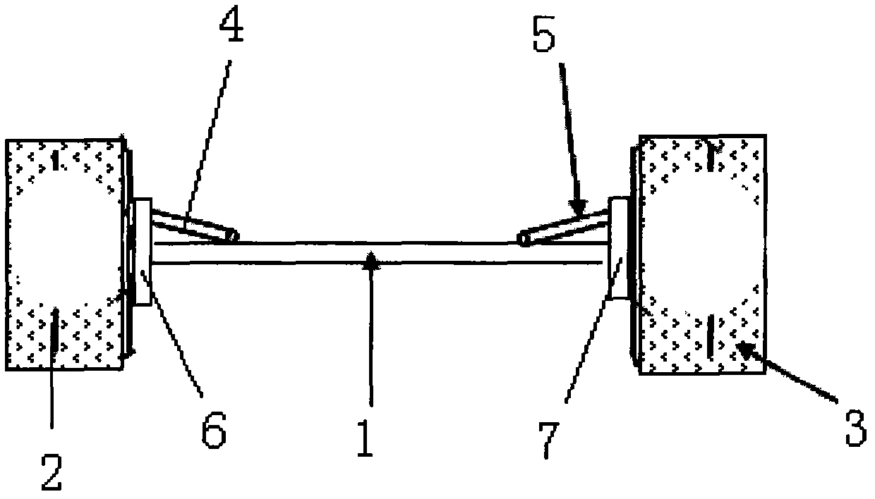
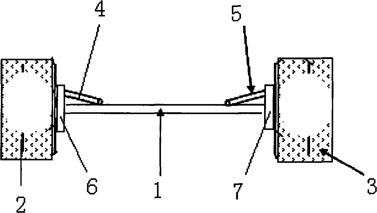
[0018] Such as figure 1 As shown, the torsion beam suspension of this embodiment includes a pair of suspensions distributed on the left and right sides of the vehicle and extending along the front and rear directions of the vehicle. 1. The right suspension trailing arm and the torsion beam 1 extending along the width direction of the vehicle, the two ends in the length direction are respectively connected to the left and right suspension trailing arms, and the length-adjustable left adjustment rod 4 is symmetrically installed on the torsion beam 1. Right adjustment rod 5, one end of the left adjustment rod 4 is fixedly connected with the torsion beam 1, and the other end is connected with the top of the steering knuckle 6 of the wheel 2 on the same side; one end of the right adjustment rod 5 is fixedly connected with the torsion beam 1, The other end is connected with the top of the steering knuckle 7 of the same side wheel 3 (the left and right suspension trailing arms are no...


PUM


Abstract

The invention provides a torsion beam suspension capable of adjusting the camber angle of a wheel. The torsion beam suspension comprises a pair of left and right suspension longitudinal arms and a torsion beam, wherein the left and right suspension longitudinal arms are distributed on the left side and right side of a vehicle and extend along the forward and backward directions of the vehicle; the front end of each longitudinal arm is supported on a vehicle body through a rubber bushing, and the back end of each longitudinal arm supports a back wheel; the torsion beam extends along the width direction of the vehicle; and the two ends of the torsion beam in the length direction are connected with the left and right suspension longitudinal arms respectively. Key points are that: left and right length-adjustable adjusting levers are arranged on the torsion beam; and one end of each adjusting lever is fixedly connected with the torsion beam, and the other end of each adjusting lever is connected with a steering knuckle of a wheel on the same side as the adjusting lever. The torsion beam suspension is provided with a pair of length-adjustable adjusting levers compared with the ordinary torsion beam suspension, has a simple structure and is easy to realize; and the camber angle of the wheel can be changed by changing the length of the adjusting lever, so that the entire dynamics performance of the suspension is enhanced, the operation stability and comfort of the entire vehicle are enhanced effectively and wear of a tire is reduced.

Description

technical field [0001] The invention belongs to the technical field of automobile manufacturing, in particular to the torsion beam suspension of automobiles. Background technique [0002] The camber angle of a car refers to the angle between the vertical center plane of the car and the intersection line between the centerline plane of the wheel and the ground. The difference in camber angle can change the contact point and force application point between the tire and the ground, directly affect the grip and wear of the tire, and change the force distribution of the vehicle weight on the axle to avoid abnormal wear of the bearing. In addition, the existence of the camber angle can be used to offset the angle change caused by the deformation of the suspension system parts and the clearance of the movable surface after the body load is applied. The existence of the camber angle will also affect the direction of travel of the car, just as a motorcycle can turn by tilting the bo...

Claims


Application Information

Patent Timeline
Patent Type & Authority Applications(China)
IPC IPC(8): B60G11/20
Inventor 侯炜
Owner CHERY AUTOMOBILE CO LTD
Why Eureka
Try Eureka