Spinning machine

A kind of machinery and spinning technology, applied in the field of spinning machinery, can solve problems such as broken yarn, low yarn strength, and reduced operating efficiency of spinning machinery, so as to achieve the effect of reducing failure and improving operating efficiency

Active Publication Date: 2011-03-30
MURATA MASCH LTD
View PDF8 Cites 21 Cited by
  • Summary
  • Abstract
  • Description
  • Claims
  • Application Information

AI Technical Summary

Problems solved by technology

This kind of spinning machine cannot (like Patent Document 1) use the yarn feeding device to clamp the yarn from the spinning device to generate a true twisted yarn during the piecing operation.
Therefore, since no real twist is added to the yarn ejected from the spinning device by being caught by the suction tube, the yarn strength is rather low
As a result, yarn breakage is likely to occur when the yarn end is caught by the suction pipe and guided to the yarn splicing device, and this splicing error is considered to greatly reduce the operation efficiency of the spinning machine.

Method used


Image

  • Spinning machine
  • Spinning machine
  • Spinning machine

Examples


Embodiment Construction

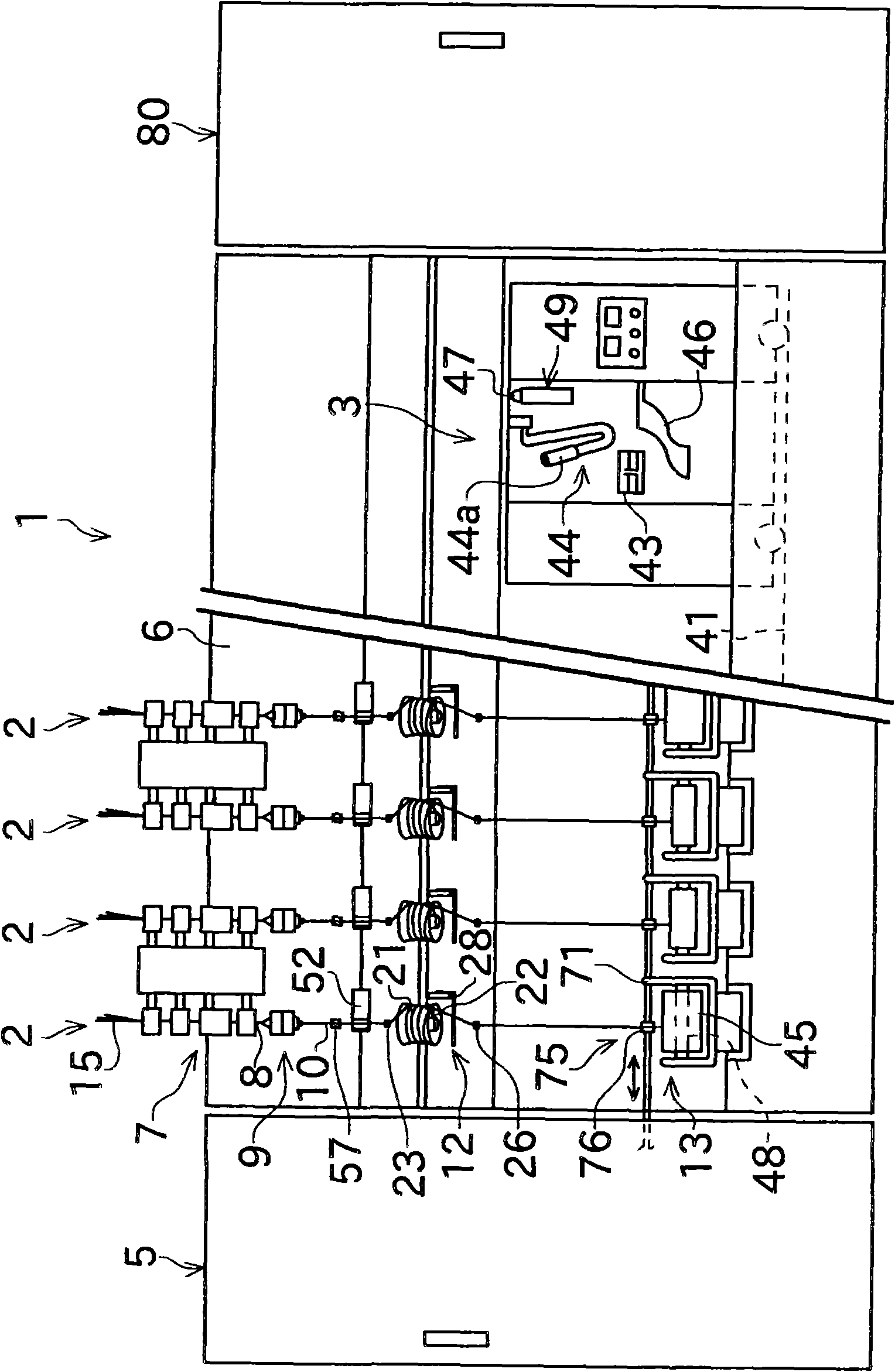
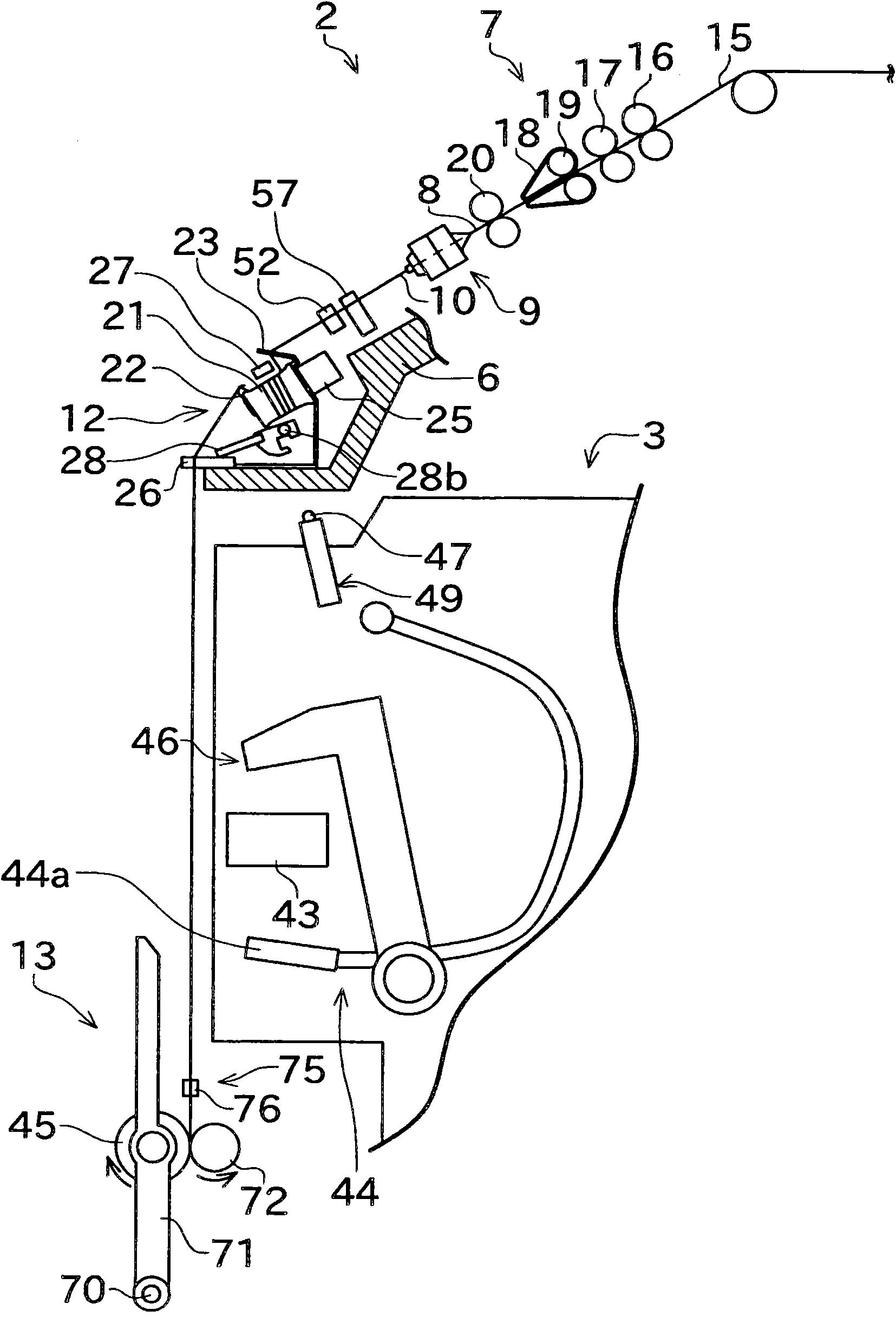
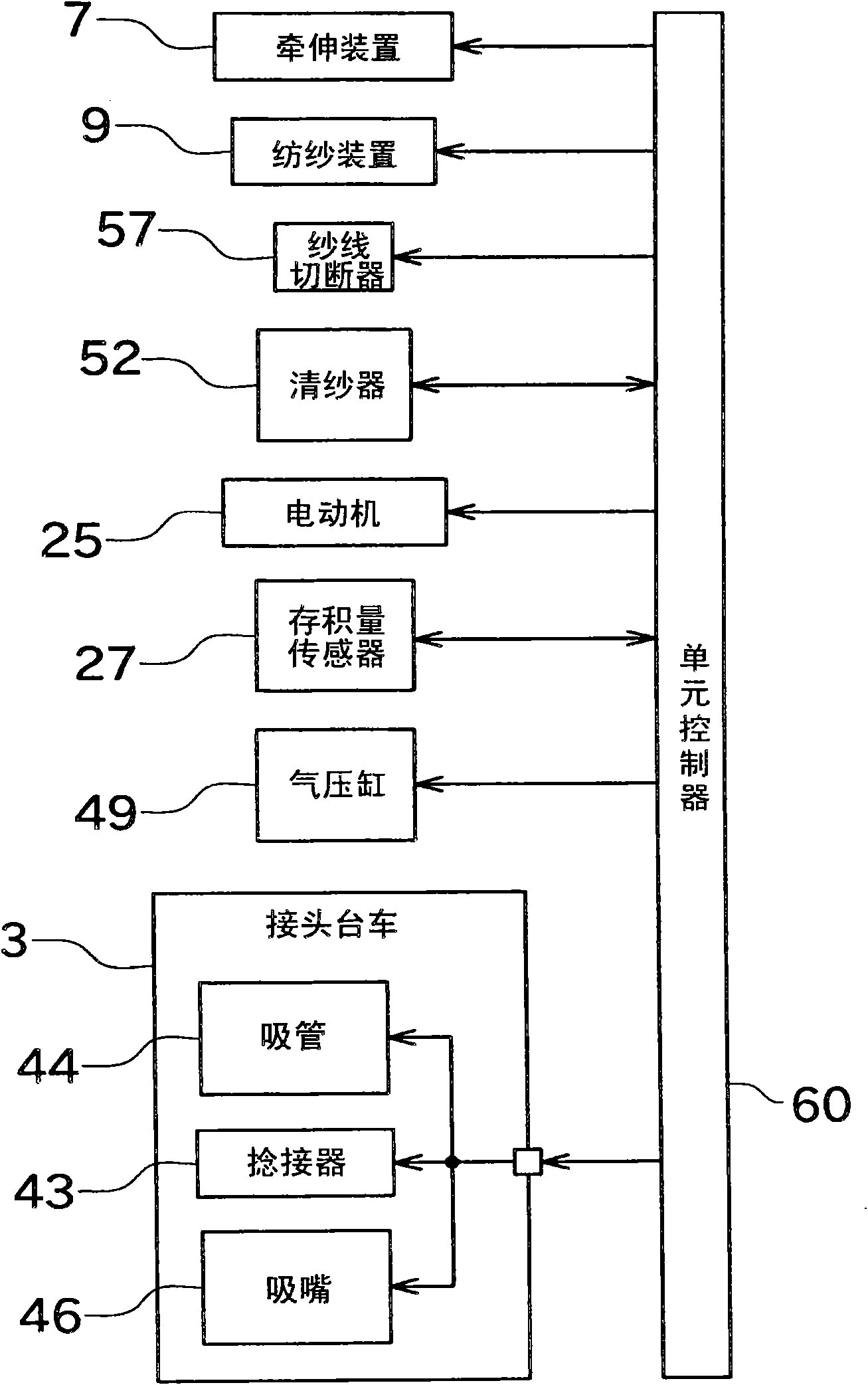
[0035]Next, a spinning frame (spinning machine) 1 according to an embodiment of the present invention will be described with reference to the drawings. In this description, "upstream" and "downstream" refer to upstream and downstream in the yarn running direction during the spinning operation. figure 1 It is a perspective view showing the overall structure of the fine spinning machine 1 . figure 2 It is a longitudinal sectional view of the spinning frame 1. image 3 It is a block diagram showing the main structure of the spinning machine.

[0036] figure 1 The spinning machine 1 shown as a spinning machine has a plurality of spindles (units) (spinning units) 2 arranged in parallel. The spinning machine 1 has a yarn splicing cart 3 , a blower box 80 and a motor box 5 .

[0037] Such as figure 1 As shown, each spinning unit 2 has a draft device (draft device) 7, a spinning device (spinning device) 9, a yarn accumulating device (yarn accumulating device) 12 and a winding de...


PUM


Abstract

The present invention provides a spinning machine, including a yarn accumulating roller (21), a yarn hooking member, a yarn removing lever (28), a suction pipe (44), and a unit controller. The hooking member can wind a spun yarn (10) around the yarn accumulating roller (21). The yarn removing lever (28) can remove the spun yarn (10) from the yarn hooking member. The suction pipe (44) can catch a yarn end of the spun yarn (10) and includes a twisting nozzle capable of applying twists to the caught spun yarn (10). The unit controller controls the twisting nozzle to operate while the spun yarn (10) caught by the suction pipe (44) is being wound around the yarn accumulating roller (21), and controls the twisting nozzle to stop before the yarn removing lever (28) removes the spun yarn (10) from the yarn hooking member.

Description

technical field [0001] The invention relates to a spinning machine with a yarn end catching device. Background technique [0002] Patent Document 1 discloses such a spinning machine. The spinning machine in Patent Document 1 has a spinning device, a yarn feeding device, a winding device, and a yarn splicing cart as main structures. [0003] The yarn feeding device has delivery rollers and nip rollers. The yarn feeding device sends the spun yarn to the winding device side by pinching the yarn (spun yarn) fed from the spinning device between the delivery roller and the nip roller and driving the delivery roller to rotate. [0004] The splicing trolley has a yarn splicing device and a suction pipe. The suction pipe can suck and catch the yarn end discharged from the spinning device to guide it to the yarn splicing device for the yarn splicing device to perform yarn splicing operation. [0005] In the structure of Patent Document 1, the yarn end is ejected from the spinning ...

Claims


Application Information

Patent Timeline
Patent Type & Authority Applications(China)
IPC IPC(8): D01H4/48B65H69/00
CPCB65H2701/31B65H51/22B65H54/26D01H15/00B65H67/081D01H4/48
Inventor 冈正毅
Owner MURATA MASCH LTD
Why Eureka
Try Eureka