Double-purpose window with functions of theft resistance and escape

A dual-purpose, window-shaped technology, applied in the field of anti-theft and escape dual-purpose windows, to achieve the effect of safe and reliable anti-theft performance, simple structure, and quick and convenient opening

Inactive Publication Date: 2011-03-30
王义斌
View PDF7 Cites 8 Cited by
  • Summary
  • Abstract
  • Description
  • Claims
  • Application Information

AI Technical Summary

Problems solved by technology

Although the above-mentioned utility model can meet an unexpected situation, the anti-theft door after it is opened can freely hang down as a ladder, and people can hide on the ladder. Although the safety degree has been improved, it is still necessary to use life-saving equipment and tools to escape.

Method used


Image

  • Double-purpose window with functions of theft resistance and escape
  • Double-purpose window with functions of theft resistance and escape
  • Double-purpose window with functions of theft resistance and escape

Examples


Embodiment 1

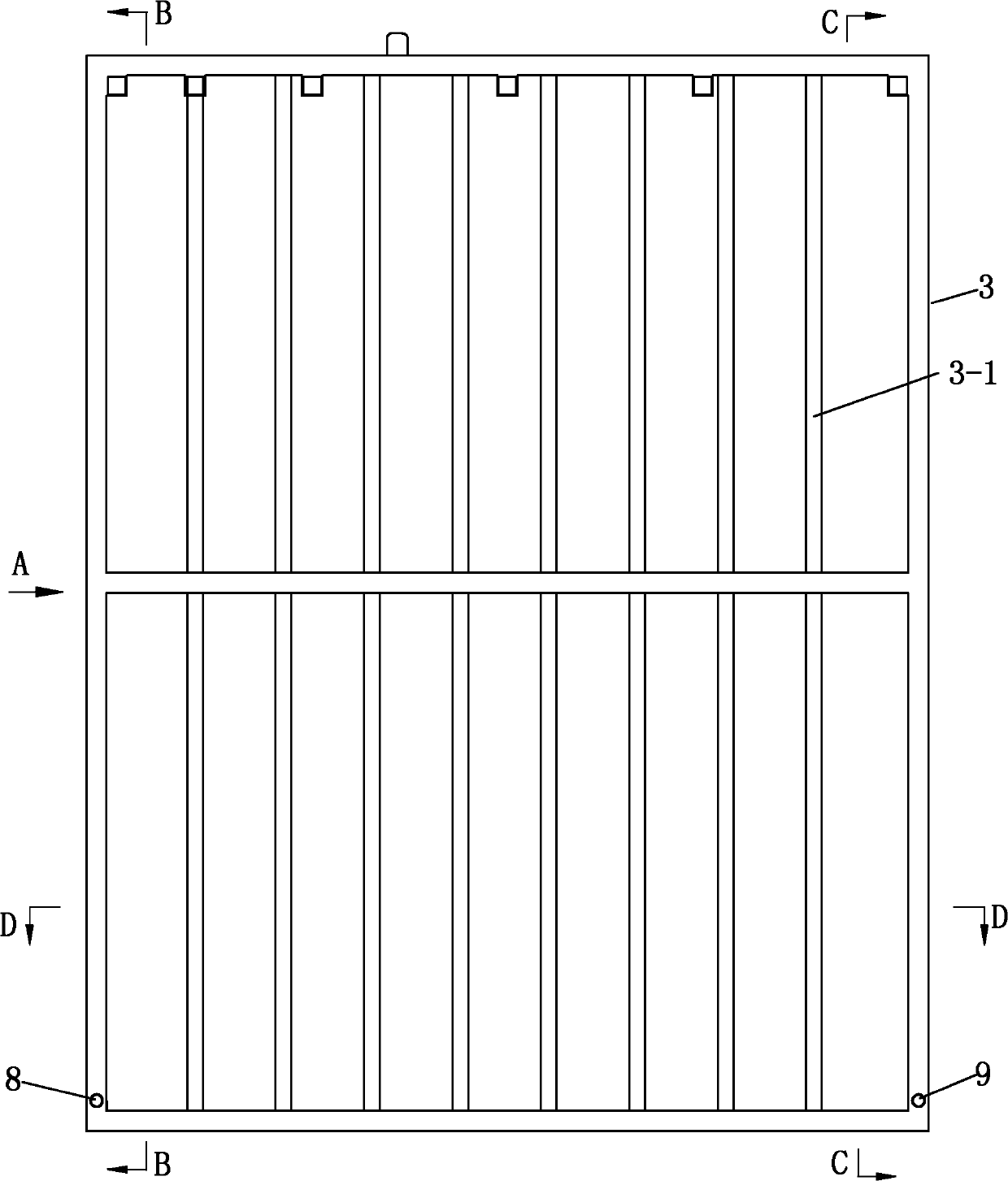
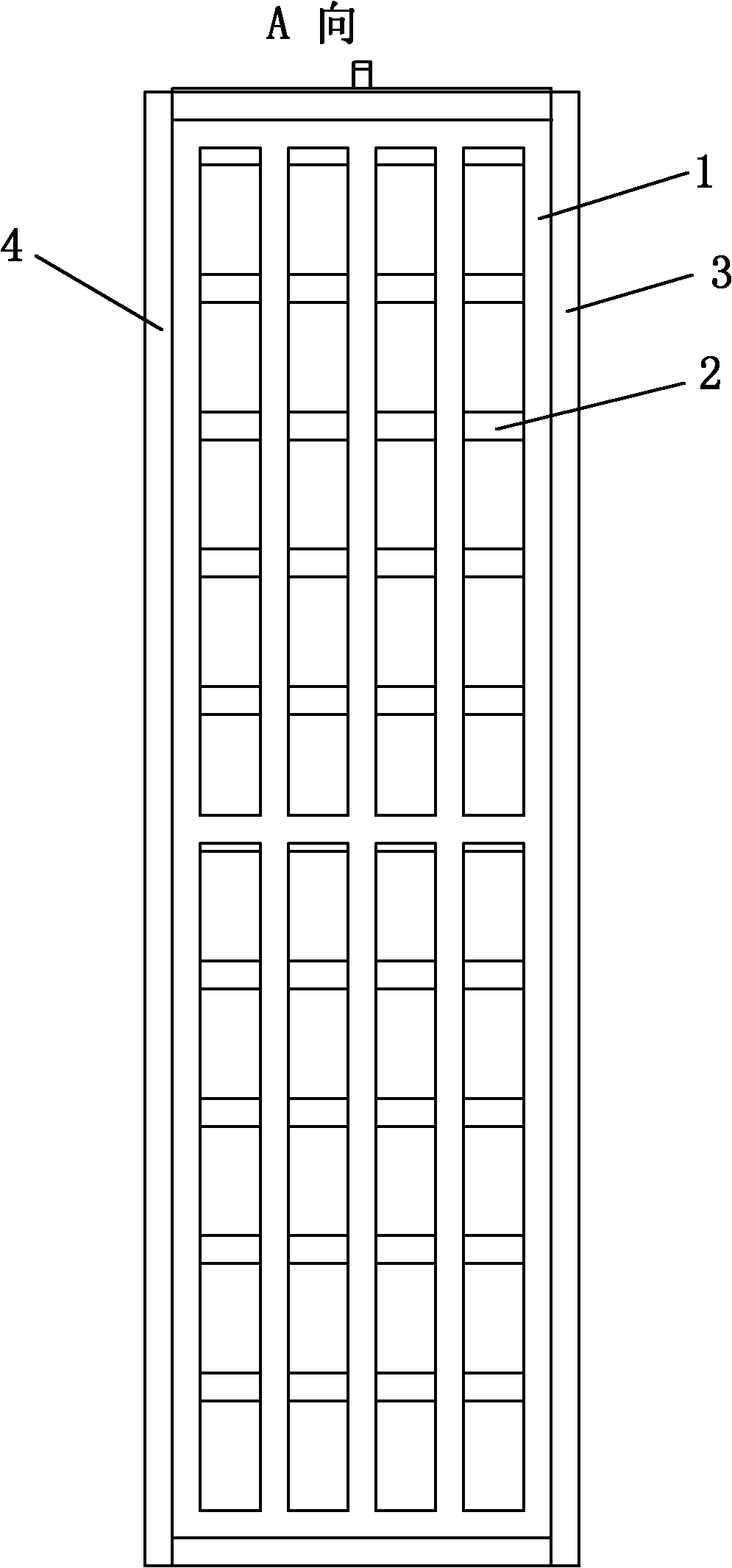
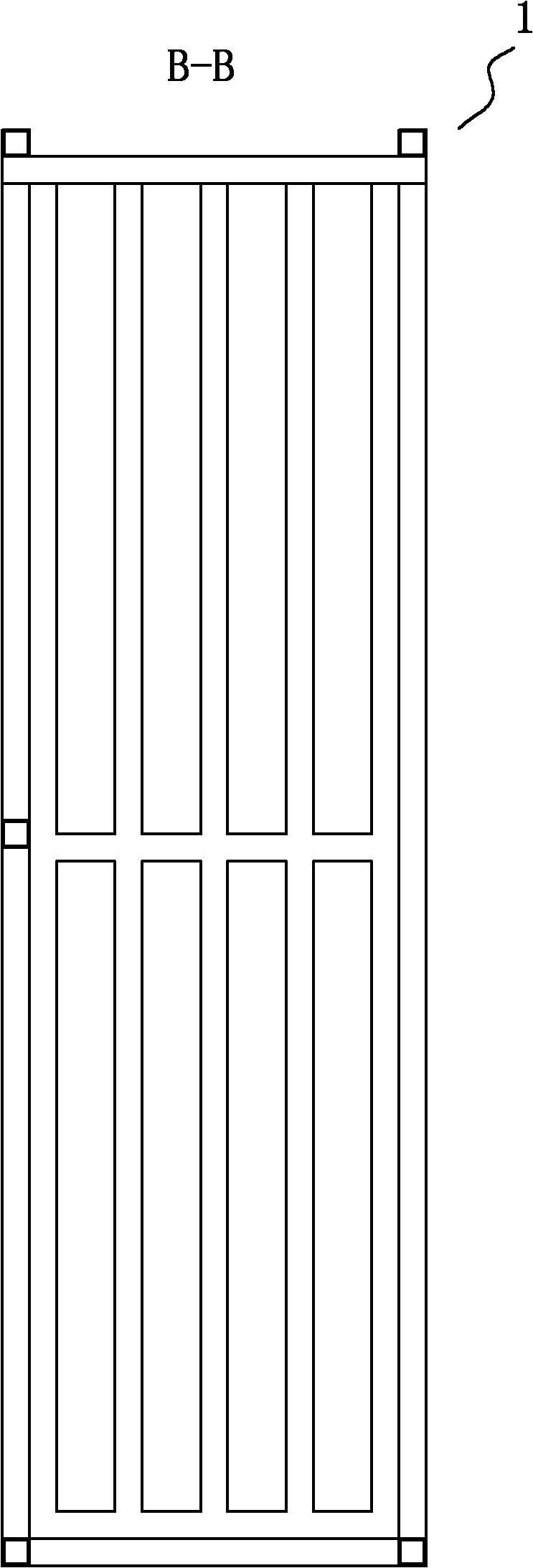
[0035] Figure 1 to Figure 8 , the shown anti-theft and escape dual-purpose window includes a convex window, the window has a front frame 3 and a rear frame 4, and a top fence 3-2 and a bottom fence 3-3 are arranged between the front frame 3 and the rear frame 4 , the bars that make up the top fence and the bars that make up the bottom fence are both oriented forward and backward. The front frame 3 is provided with a front fence 3-1, and the form is fixed on the body of wall 5 through the rear frame 4. No. 1 fence gate 1 and No. 2 fence gate 2 are respectively arranged on the left and right sides of the form. Wherein the fence bar 2-0 of No. 2 fence gate 2 is horizontally arranged forward and backward.

[0036] The lower end of the No. 1 fence gate is connected between the front and rear frames 3 and 4 of the side by the No. 1 pin shaft 8, and an electric lock 7 is provided on the top fence of the form. The No. 1 fence gate 1 The top end is provided with a lock catch, and t...

Embodiment 2

[0041] See Figure 9 to Figure 11 , the No. 2 fence gate is mobile, and the two sides of the No. 2 fence gate 2 are respectively provided with guide protrusions 2-4, and the front and rear frames of the side are respectively provided with guide grooves, and the guide grooves of the No. 2 fence gate The convex strip cooperates with the guide groove, so that No. 2 fence gate 2 slides along the guide groove of the front and rear frames. An electric lock is provided on the top fence of the window, and a lock catch is provided on the uppermost end of the No. 2 fence gate. The lock catch of the electric lock and the No. 2 fence gate is connected to connect the No. 2 fence gate 2 with the top of the form. All the other are identical with embodiment 1.

Embodiment 3

[0043] See Figure 14 and Figure 15 , The electric lock 7 used in this embodiment has a housing 7-1, a bar-shaped bolt 7-15 and a rotating plate 7-16. The bottom of the rotating plate 7-16 is connected on the housing 7-1 by the pin shaft 7-19, the pin shaft 7-19 is provided with a torsion spring 1-18, and the upper end and the rear end of the rotating plate 7-16 are respectively provided with a guide Pin 7-20 and top post 7-17, bar-shaped dead bolt 7-15 is provided with waist-shaped groove 7-15-1, and guide pin 7-20 inserts the waist-shaped groove 7-15 of bar-shaped dead bolt 7-15 In -1, a spare battery 7-6, an electric control module 7-7, an acousto-optic alarm 7-14 and an electromagnet 7-2 at the rear side of the rotating plate 7-16 are also provided in the housing 7-1. The front end of the sliding pad iron of iron 7-2 connects a push rod 7-4, and the sliding pad iron is provided with spring 7-10. When the push rod 7-4 was in the extended state, the front end of the push...


PUM


Abstract

The invention relates to a double-purpose window with the functions of theft resistance and escape, which is characterized in that the window body comprises a front frame and a rear frame, wherein a top fence and a bottom fence are arranged between the front frame and the rear frame; a front-face fence is arranged in the front frame; the window body is fixed on a wall body through the rear frame; the left and the right sides of the window body are respectively provided with a No.1 fence door and a No.2 fence door; the No.1 fence door and the No.2 fence door are respectively and flexibly connected between the front frame and the rear frame on the side; the No.1 fence door is open, is in a horizontal state and is supported through the bracket fixed on the wall body so as to form a platform; the No.2 fence door is open and in a pendulous state to form an escape ladder; and the No.1 fence door and the No.2 fence door are respectively connected to the corresponding positions of the window body through an electric lock. The invention improves the common convex type anti-theft window so as to have the anti-theft function and form the escape ladder and the platform after being expanded, utilizes the bottom fence of the window as a transition channel so as to open an escape channel on the external wall body of a building, and is not required to be provided with an additional escape tool to solve the escape problem when a high-rise building is on fire.

Description

technical field [0001] The invention relates to a dual-purpose window for anti-theft and escape. Background technique [0002] Fire science and technology workers and firefighters at home and abroad have worked hard for many years, while constantly improving the fire protection design specifications of high-rise buildings, they have also carried out extensive research and development on high-rise life-saving equipment. However, the life-saving equipment and tools currently developed require additional equipment and are expensive. In addition, due to installation problems and regular maintenance, it is difficult to enter the homes of ordinary people. Residential houses in my country are equipped with anti-theft windows more, and people are trapped in the house because the anti-theft windows cannot be opened in the fire, and the tragic scene that cannot escape and cannot be rescued also takes place. Chinese patent No. 99217670.0 utility model patent specification discloses a ...

Claims


Application Information

Patent Timeline
Patent Type & Authority Applications(China)
IPC IPC(8): E06B5/11E06C9/10E05B47/02
Inventor 王义斌
Owner 王义斌
Why Eureka
Try Eureka