Supercharge Your Innovation With Domain-Expert AI Agents!

Method of controlling fuel in an exhaust treatment system implementing temporary engine control

An engine system and exhaust gas treatment technology, which is applied to the electronic control of exhaust gas treatment devices, exhaust gas treatment, engine components, etc., can solve the problem of high fuel consumption

Inactive Publication Date: 2011-03-30
CATERPILLAR INC
View PDF7 Cites 1 Cited by
  • Summary
  • Abstract
  • Description
  • Claims
  • Application Information

AI Technical Summary

Problems solved by technology

Additionally, regeneration of the particulate filter can negatively impact other aspects of engine performance (i.e., power output, fuel consumption, etc.) and / or unintended effects of
Also, during regeneration, a large amount of fuel is consumed as the fuel burning burner heats all the exhaust from the power source

Method used


Image

  • Method of controlling fuel in an exhaust treatment system implementing temporary engine control
  • Method of controlling fuel in an exhaust treatment system implementing temporary engine control

Examples


Embodiment Construction

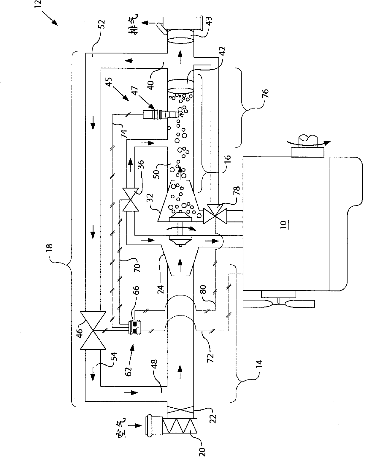
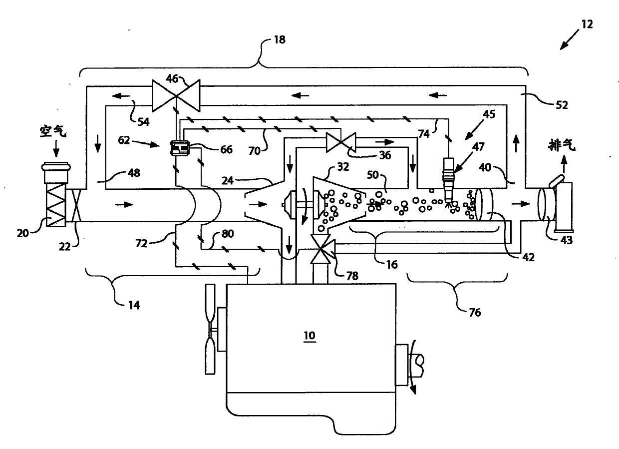
[0013] figure 1 A power source 10 is shown having an exemplary exhaust treatment system 12 . The power source 10 may be embodied as an engine, such as a diesel engine, a gasoline engine, an engine powered by gaseous fuel such as a natural gas engine, or any other engine obvious to those skilled in the art. Alternatively, power source 10 may embody a power source other than an engine, such as a furnace. Exhaust treatment system 12 may include an intake line 14 , an exhaust line 16 , and a recirculation line 18 coupled to power source 10 for transferring fluid to and from power source 10 .

[0014] Intake line 14 may include a device for introducing charge into a combustion chamber (not shown) of power source 10 . For example, intake line 14 may include an air cleaner 20 and an intake valve 22 fluidly coupled upstream of one or more compressors 24 . It is conceivable to include additional and / or different components in the intake line 14, for example, one or more air coolers ...


PUM


Abstract

The invention relates to a method of controlling fuel in an exhaust treatment system implementing temporary engine control. An exhaust treatment system associated with a power source is disclosed. The exhaust treatment system may have a filter located to remove particulate matter from a flow of exhaust, and a regeneration device located proximal the filter. The exhaust treatment system may also have a first fluid handling component located upstream of the power source to vary an amount of oxygen in the flow of exhaust, a second fluid handling component located downstream of the power source to vary the amount of exhaust air flow in the exhaust circuit, and a controller in communication with the regeneration device and the fluid handling component. The controller may determine a need for filter regeneration, and determine adjustments to the first and second fluid handling components required to provide sufficient oxygen and air mass flow in the exhaust for filter regeneration. The controller may further determine an effect the adjustments will have on operation of the power source, and determine corrections for the power source to account for the effects. The controller may substantially simultaneously implement the adjustments and the corrections.

Description

technical field [0001] The present invention relates generally to an exhaust treatment system, and more particularly to a method of fuel control in an exhaust treatment system implementing temporary engine control. Background technique [0002] Complex mixtures of air pollutants are emitted by engines, including diesel engines, gasoline engines, natural gas engines, and others known in the art. Air pollutants can consist of gases and solid materials, including nitrogen oxides (NOx) and particulate matter. As environmental concerns increase, exhaust emission standards become more stringent, and the amount of NOx and particulate matter emitted from an engine may be regulated depending on the type of engine, the size of the engine, and / or the rating of the engine. [0003] One approach that engine manufacturers have implemented in order to comply with regulations on NOx emissions to the environment is to recirculate exhaust gas expelled from the engine back into the engine for...

Claims


Application Information

Patent Timeline
Patent Type & Authority Applications(China)
IPC IPC(8): F01N9/00F01N3/025
CPCF02B37/183F01N3/029F01N3/0253F01N3/0256F01N2410/04F01N3/0842F01N3/032F02M25/0718Y02T10/144Y02T10/121F02B37/16F02B37/013F02M26/15Y02T10/12
Inventor D·卡帕洛斯
Owner CATERPILLAR INC
Features
  • R&D
  • Intellectual Property
  • Life Sciences
  • Materials
  • Tech Scout
  • Unparalleled Data Quality
  • Higher Quality Content
  • 60% Fewer Hallucinations
Learn More