
Electrical cable wiring head device and electrical cable wiring apparatus

A wiring equipment and wiring technology, applied in the direction of electrical components, electrical components, etc., can solve the problems of prolonged time period, floating of covered cables, etc., to achieve the effect of reducing the number of times, connecting quickly, and suppressing the floating of wiring boards

Inactive Publication Date: 2011-03-30
SUMITOMO WIRING SYST LTD
View PDF7 Cites 3 Cited by
  • Summary
  • Abstract
  • Description
  • Claims
  • Application Information

AI Technical Summary

Problems solved by technology

[0006] However, according to the technique disclosed in JP-A-10-224951, since the third guide roller for guiding the covered cable is arranged on the rear side of the rotation axis of the head in the routing direction and at a higher level than the bottom surface of the head position, so when the head moves, there is a problem that the covered cable floats largely from the wiring board
Thus, there is a problem that the time period required for wiring will be extended
[0007] According to the technique disclosed in JP-A-2007-53847, since the covered cable can be pressed onto the wiring board only when the head moves linearly in the X-axis direction or the Y-axis direction, there is a problem that the covered cable is likely to bend dots etc. float from the wiring board

Method used


Image

  • Electrical cable wiring head device and electrical cable wiring apparatus
  • Electrical cable wiring head device and electrical cable wiring apparatus
  • Electrical cable wiring head device and electrical cable wiring apparatus

Examples


Embodiment Construction

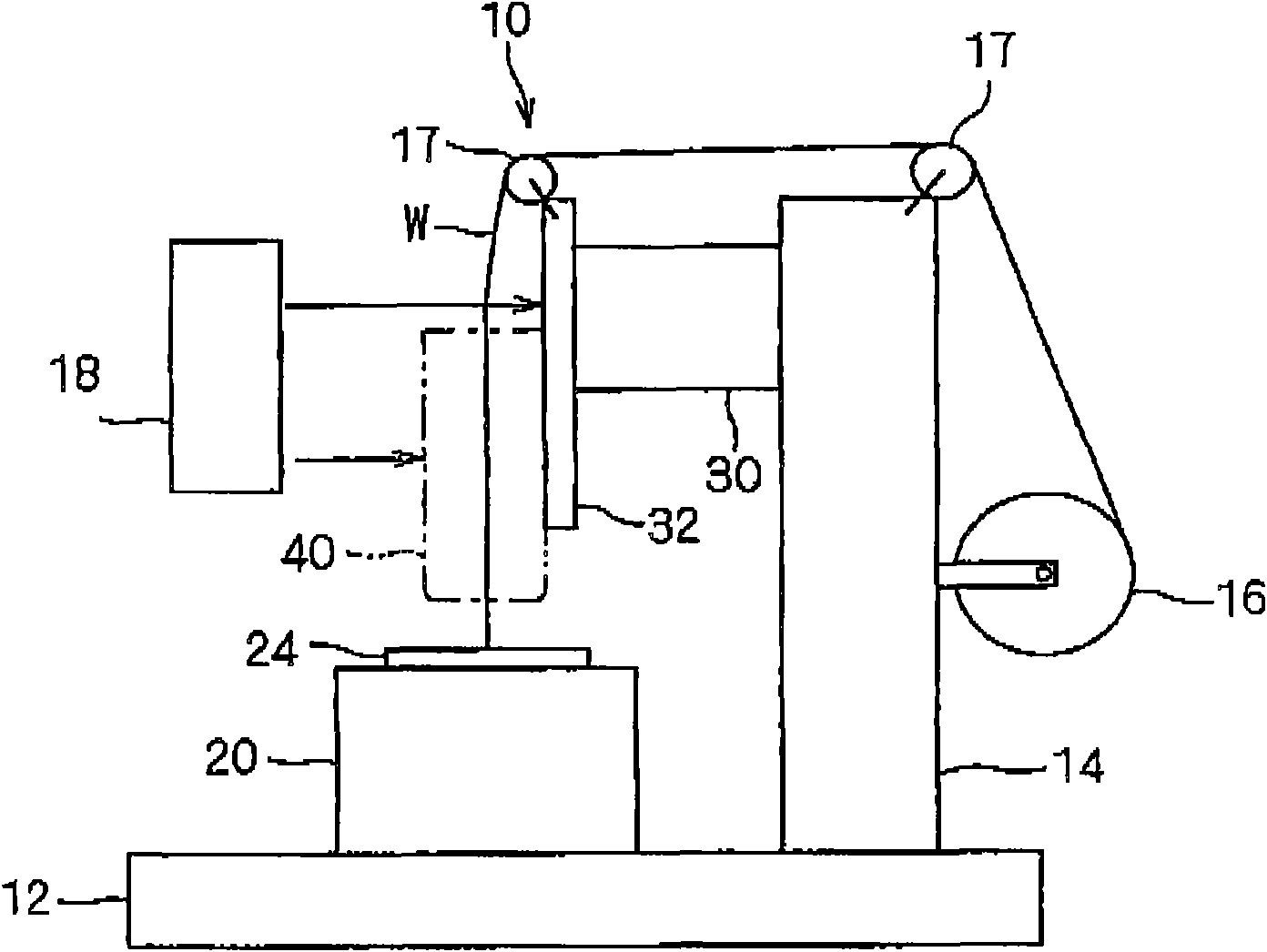
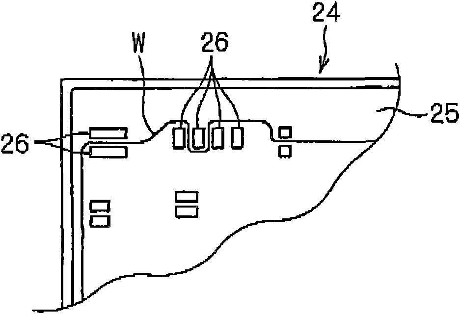
[0026] Referring now to the accompanying drawings, embodiments of a cable routing head device and a cable routing device including the same according to the present invention will be described below. figure 1 It is an explanatory diagram showing the whole of the cable distribution equipment 10 . figure 2 is a schematic plan view showing a part of the wiring board 24 as a wiring target.

[0027] First, the general general configuration of the cable routing device 10 will be described below. The cable wiring apparatus 10 includes a cable wiring head device 40 , a wiring board seating part 20 and a wiring driving part 30 .

[0028] The wiring board placement portion 20 functions as a wiring object holding portion that holds the wiring board 24 (wiring object) at a given position in a given posture. The wiring board seating part 20 is fixed on the given base 12 . The wiring board 24 is held on the wiring board seating portion 20 by a fitting structure, a well-known locking str...


PUM


Abstract

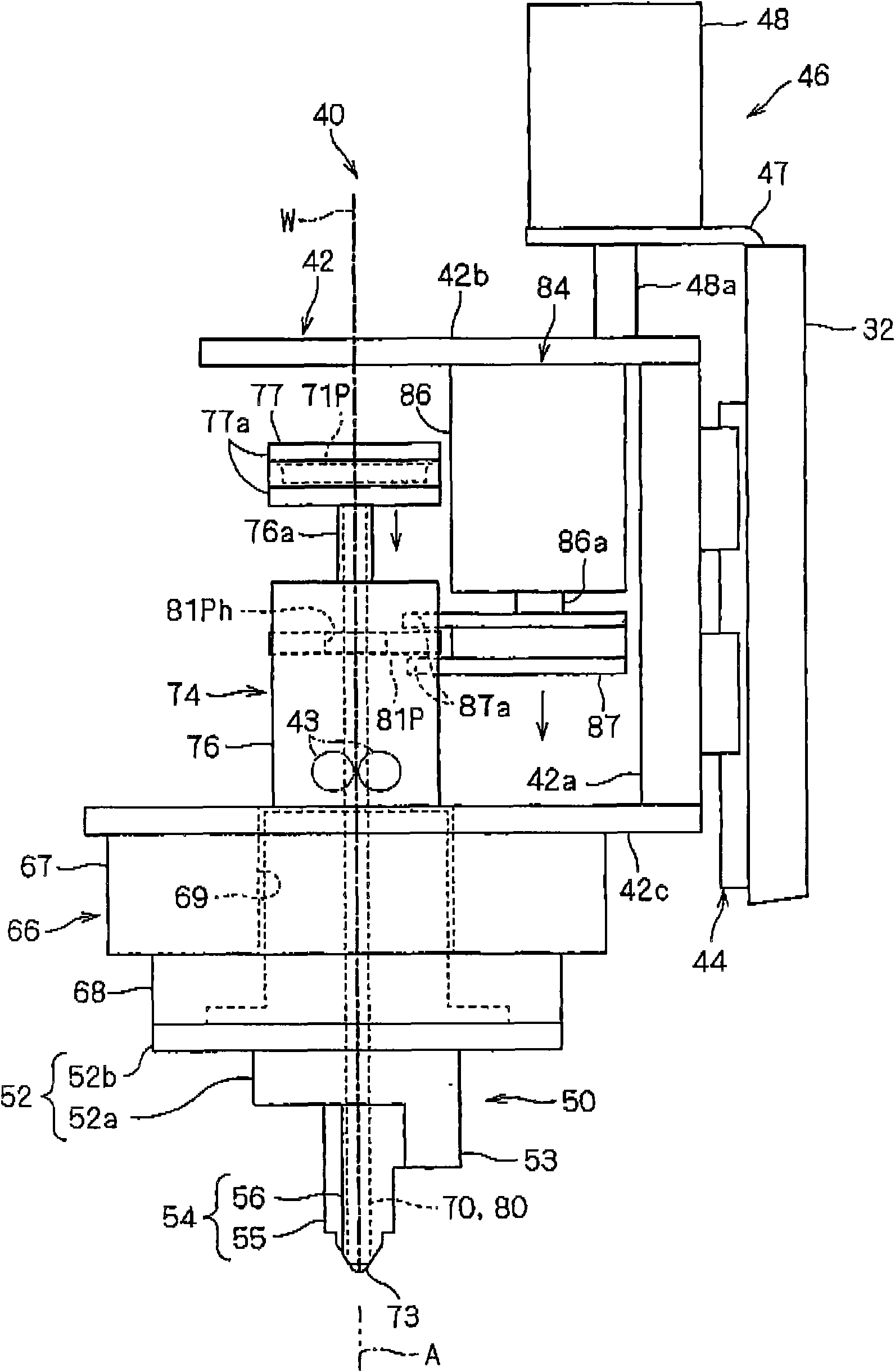
An electrical cable wiring head apparatus is provided to rapidly wire an electrical cable while more effectively restraining the electrical cable from floating. An electrical cable wiring head device of the electrical cable wiring head apparatus moves along a wiring surface of a wiring plate to wire an electrical cable on the wiring surface. The electrical cable wiring head device comprises: a head section supported rotatably about a rotary axis and provided with a guide recess for leading the electrical cable to the wiring surface, the guide recess being offset from the rotary axis; a head rotating mechanism for rotating the head section; a guide pushing member including a shaft portion and a roller portion provided rotatably on a distal end of the shaft portion, the guide pushing member being supported movably along the rotary axis; and a guide pushing member drive mechanism for reciprocating the guide pushing member.

Description

[0001] Cross References to Related Applications [0002] This application claims priority from JP2009-182386 filed in Japan on Aug. 5, 2009, the entire disclosure of which is hereby incorporated by reference. technical field [0003] The present invention relates to a technique for manufacturing a circuit component provided with a wiring cable, such as an electrical junction box or the like used as an automotive component. Background technique [0004] Various cable routing devices are known in the prior art. For example, JP-A-10-224951 discloses a cable wiring device in which a head for feeding a covered cable is rotatably supported, and a push pin and a third guide roller are connected to the The head is combined. The third guide roller is arranged on the rear side of the rotation axis of the head in the wiring direction and at a position higher than the bottom surface of the head. When the head moves, the covered cable is drawn out from the head while being guided by t...

Claims


Application Information

Patent Timeline
Patent Type & Authority Applications(China)
IPC IPC(8): H02G3/16H02G3/08
CPCH05K13/06H02G3/08H02G3/16Y10T29/53261Y10T29/5187Y10T29/53174Y10T29/532Y10T29/53213
Inventor 谷德之大石明典
Owner SUMITOMO WIRING SYST LTD
Learn More