Method for rapidly distinguishing CT wire break in bus protection

A busbar protection, fast technology, applied in the direction of measuring devices, instruments, measuring electricity, etc., can solve the problems of inability to locate the CT disconnection interval and its phase difference, differential protection misoperation, etc.

Active Publication Date: 2011-04-06
NANJING GUODIAN NANZI POWER GRID AUTOMATION CO LTD
View PDF4 Cites 28 Cited by
  • Summary
  • Abstract
  • Description
  • Claims
  • Application Information

AI Technical Summary

Problems solved by technology

This method only monitors the differential current, does not judge the current of the interval connected to the busbar protection, and cannot locate the interval and phase difference of the CT disconnection
Since it takes a second-level delay to judge the disconnection of the CT, the disconnection of the CT in the large current interval often leads to the misoperation of the differential protection

Method used


Image

  • Method for rapidly distinguishing CT wire break in bus protection
  • Method for rapidly distinguishing CT wire break in bus protection
  • Method for rapidly distinguishing CT wire break in bus protection

Examples


Embodiment Construction

[0049] The technical solution of the present invention will be described in detail according to the accompanying drawings.

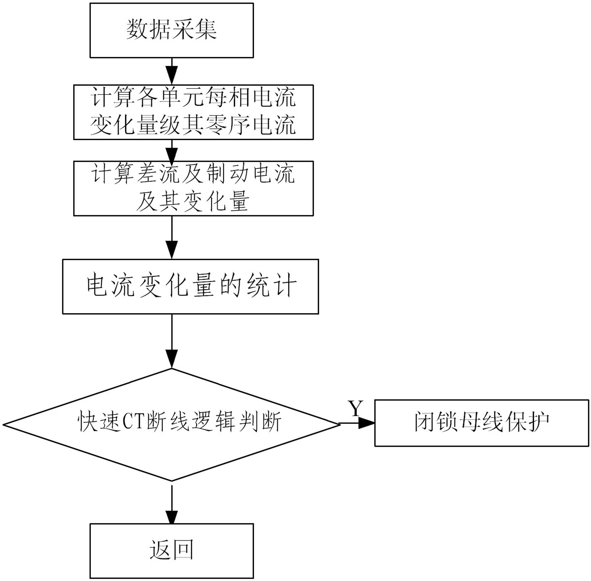
[0050] The invention discloses a method for fast CT disconnection protection of a current variation busbar, which comprises the following steps (such as image 3 shown):

[0051] Step 1. Data collection:

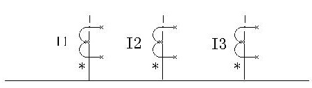
[0052] The A, B, C three-phase current of each connection unit on the bus is sampled at a constant sampling frequency. All connecting units on the bus are shown in the attached figure 1 Shown: Taking a single busbar as an example, the connection units are I1, I2, I3, where I1, I2, and I3 can be defined as main transformers, lines, etc.

[0053] Step 2. Calculate the current variation and zero-sequence current of each unit in each phase:

[0054] Calculate the A, B, C three-phase current variation of each connected unit on the bus respectively, and then compare the current variation with the preset value (K*In) to determine the direction of current ...


PUM


Abstract

The invention discloses a new bus protection method for realizing rapid CT wire break based on current variation and a complete of technical scheme. In the invention, the variations of the original current sampling values of connecting units of a bus are compared with a preset threshold to form the number of upward changed current units, the number of downward changed units and the number of units without change. By means of comparison between the number of three changed units and the variation direction of braking current, normal CT wire break and faults of the bus are distinguished, thus the CT wire break can be effectively judged and misoperation for bus protection can be prevented.

Description

technical field [0001] The invention relates to a method for quickly judging CT disconnection in busbar protection, and belongs to the technical field of electric power system automation. Background technique [0002] The current CT disconnection discrimination method used for busbar protection is that the differential current is greater than the CT disconnection lock value and a period of time delay has elapsed. This method only monitors the differential current, does not judge the current of the interval connected to the busbar protection, and cannot locate the interval and phase difference of the CT disconnection. Since a second-level delay is required to determine the disconnection of the CT, the disconnection of the CT at large current intervals often leads to misoperation of the differential protection. Contents of the invention [0003] The technical problem to be solved by the present invention is to provide a new method for fast CT disconnection judgment suitable...

Claims


Application Information

Patent Timeline
Patent Type & Authority Applications(China)
IPC IPC(8): G01R31/02G01R19/165
Inventor 康丰汪思满唐治国周小波
Owner NANJING GUODIAN NANZI POWER GRID AUTOMATION CO LTD
Why Eureka
Try Eureka