Axial flow type fan and fan wheel thereof

An axial flow and fan technology, which can be used in axial flow pumps, non-variable volume pumps, non-displacement pumps, etc., and can solve problems such as inability to generate air volume.

Active Publication Date: 2011-04-13
SUNONWEALTH ELECTRIC MACHINE IND
View PDF1 Cites 9 Cited by
  • Summary
  • Abstract
  • Description
  • Claims
  • Application Information

AI Technical Summary

Problems solved by technology

Other image 3 As shown, when the control assembly 94 controls the fan wheel 92 to rotate in the forward direction, although the fan wheel 92 can still drive the air flow inside the casing 91 to flow backwards, and further discharge the gas to the casing through the air inlet portion 911 body 91 outside, so that the a

Method used


Image

  • Axial flow type fan and fan wheel thereof
  • Axial flow type fan and fan wheel thereof
  • Axial flow type fan and fan wheel thereof

Examples


Embodiment Construction

[0056] In order to make the above-mentioned and other objects, features and advantages of the present invention more comprehensible, the preferred embodiments of the present invention are specifically cited below, together with the accompanying drawings, as follows:

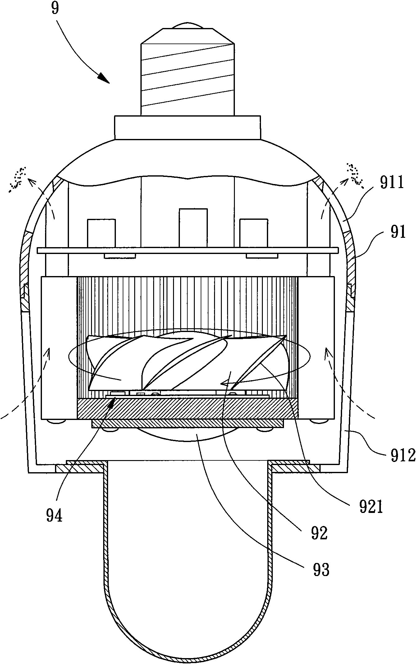
[0057] Please refer to Figure 4 As shown, the axial flow fan of the present invention includes a fan wheel 1a, a fan frame 3, a permanent magnet 4 and a stator 5.

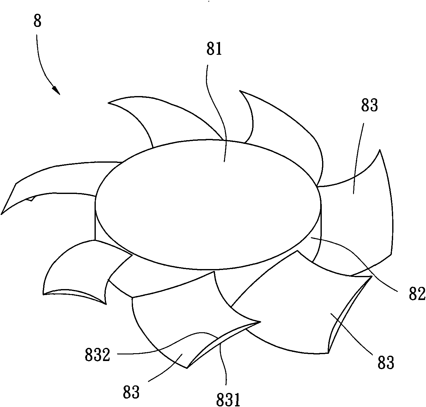
[0058] Please refer to Figure 5 and 6 As shown, the fan wheel 1 a of the first embodiment of the present invention is disclosed, and the fan wheel 1 a includes a hub 10 and several blades 20 . The hub 10 has a first end portion 11 and a second end portion 12; each of the blades 20 has a first peripheral edge 21 and a second peripheral edge 22; wherein the first peripheral edge 21 of each of the blades 20 is combined with the On the outer peripheral wall of the hub 10, the second peripheral edge 22 of each of the blades 20 extends outward for a pr...


PUM


Abstract

The invention discloses an axial flow type fan comprising a fan wheel, a fan frame, a permanent magnet and a stator. The fan wheel comprises a hub and a plurality of blades. The hub is provided with a first end part and a second end part. Each of the blades is provided with a first circumferential edge and a second circumferential edge, the first circumferential edge of each blade is connected tothe outer circumferential wall of the hub, and each blade is respectively provided with a first air driving surface and a second air driving surface. The first air driving surface forms at least one first concave part, and the second air driving surface forms at least one second concave part. The fan frame is a hollow frame in which the fan wheel can be arranged. The permanent magnet is connectedto the inner side of the hub of the fan wheel. The stator is connected to the inner side of the fan frame. Therefore, the fan wheel can produce sufficient air quantity no matter the fan wheel rotatesclockwise or anticlockwise, so that the fan wheel can be used in work places requiring double-direction air driving.

Description

technical field [0001] The present invention relates to a heat dissipation fan and its fan wheel, especially a fan wheel with a special structure designed to be suitable for an axial flow fan providing bidirectional wind driving function. Background technique [0002] The existing axial flow fans that are common on the market generally have an outer frame, and components such as a stator and a fan wheel are combined in the outer frame, so that the stator can be used to drive the fan wheel to rotate, and then a predetermined drive can be achieved. Air volume. [0003] The fan wheel of the aforementioned existing axial flow fan is roughly as the new patent of Taiwan Announcement No. 254381 "Fan Wheel Blade Structure of Small Heat Dissipating Fan". Please refer to figure 1 As shown, the existing fan wheel 8 has a circular base plate 81, a hollow ring 82 is formed on the periphery of the circular base plate 81, and several blades 83 are formed on the outer peripheral wall of t...

Claims


Application Information

Patent Timeline
IPC IPC(8): F04D19/00F04D29/32F04D29/38
Inventor 洪银树
Owner SUNONWEALTH ELECTRIC MACHINE IND
Why Eureka
Try Eureka