Hair dryer

A hair dryer and fan technology, applied in the field of hair dryers, can solve the problem of inability to reduce the noise of hair dryers, and achieve the effect of reducing manufacturing costs

Inactive Publication Date: 2015-11-25
SANFAT ELECTRIC MFG
View PDF9 Cites 4 Cited by
  • Summary
  • Abstract
  • Description
  • Claims
  • Application Information

AI Technical Summary

Problems solved by technology

[0009] In this way, in the existing hair dryer, unless it has a special structure such as a resonator, a microphone, a speaker, a signal processing device, and a curved surface installed at the top of the suction port, it is impossible to reduce the noise of the hair dryer.

Method used


Image

  • Hair dryer
  • Hair dryer
  • Hair dryer

Examples


Embodiment Construction

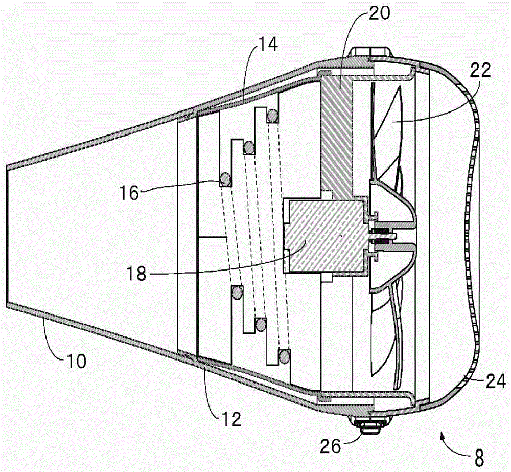
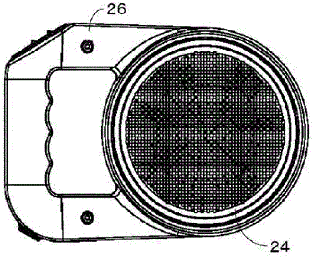
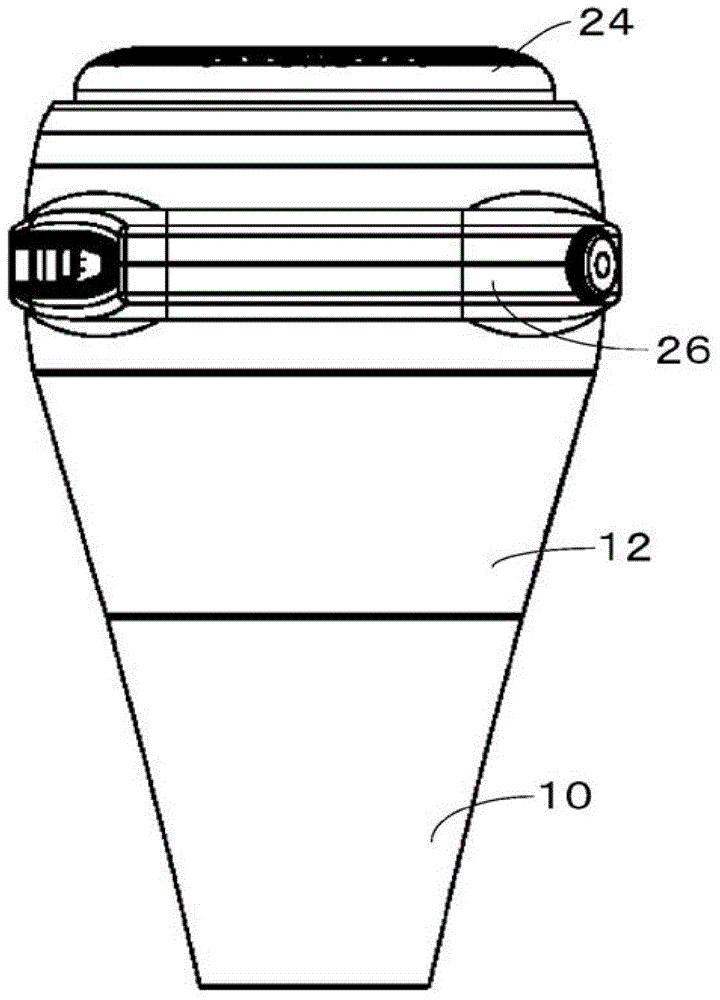
[0037] As a top view ( figure 2 ), main view ( image 3 ),right elevation( Figure 4 ),Rear view( Figure 5 ) and bottom view ( Figure 6 ), the hair dryer 8 of the present invention includes a cylindrical main body casing 12, a spout 10 disposed in front of it, a rear cover 24 disposed behind the main body casing 12, and a handle 26 disposed on the top of the main body casing 12 . The handle 26 is in a concave shape, and it is easy to hold a large hair dryer whose diameter of the fan is more than 90mm. In addition, even if the recessed handle is replaced with an L-shaped handle whose only one end is connected to the main body of the hair dryer, the effect of easily holding the hair dryer is the same. Such as figure 2 As shown, the rear cover 24 is formed with countless holes for sucking in air.

[0038] figure 1 is for Figure 4 A-A' is a sectional view of the profile of the hair dryer 8. Inside the main body casing 12 , a motor 18 is fixed through nine rectifying...


PUM


Abstract

A hair dryer (8) includes: a heater (16); a fan (22); a motor (18) for driving the fan (22); a body case (12) that accommodates the heater (16), the fan (22), and the motor (18); and a thermal barrier tube 14 disposed between the body case (12) and the heater (16). The diameter of the fan (22) is allowed to be 90 mm or more, and an air quantity formed by the fan (22) is allowed to be 1.0 m 3 to 1.4 m 3 / min, thereby enabling reduction of noise while resulting in the sufficient air quantity.

Description

technical field [0001] The present invention relates to a hair dryer that heats the air sucked by a fan through a heater, especially relates to a hair dryer that can obtain sufficient air volume and reduce noise level. Background technique [0002] A hair dryer for drying hair etc. uses a motor to rotate a fan, sucks air into the main body through the air inlet, heats the air with a heater, and discharges the air to the outside of the main body through the air outlet. When the hair dryer is driven, sometimes even 70dB of noise is generated, making it difficult to watch TV or have a conversation near it, and it also prevents a sleeping person from sleeping peacefully in the middle of the night. The main causes of the noise of the hair dryer are considered to be wind noise caused by the fan, sound from the motor, standing wave noise caused by the casing, and the like. If the rotation speed of the motor is reduced, the noise of the hair dryer can be reduced, but if the rotatio...

Claims


Application Information

Patent Timeline
Patent Type & Authority Applications(China)
IPC IPC(8): A45D20/44A45D20/12
CPCA45D20/08A45D20/10
Inventor 寺本将宪森田启德堀口雄亮彭军成
Owner SANFAT ELECTRIC MFG
Why Eureka
Try Eureka