Heat pipe radiating device used in high power LED (light emitting diode) street lamp

A technology for LED street lamps and cooling devices, which is applied to cooling/heating devices of lighting devices, lighting devices, lighting and heating equipment, etc. It can solve the problems of slow heat dissipation, volatilization, and failure of cooling devices to dissipate heat normally, so as to save construction costs, The effect of prolonging the service life and protecting from burning

Inactive Publication Date: 2012-07-11
王凯军
View PDF4 Cites 0 Cited by
  • Summary
  • Abstract
  • Description
  • Claims
  • Application Information

AI Technical Summary

Problems solved by technology

[0003] The invention aims to solve the technical problem that the heat dissipation device of the LED street lamp cannot dissipate heat normally due to the aging of the heat pipe, and even burns the LED lamp body and the circuit board due to heat accumulation at the lamp body, and designs a heat pipe heat dissipation used in high-power LED street lamps. The device, by adding the negative pressure adjustment interface of the heat pipe and the supplementary mechanism of the heat transfer medium in the heat pipe cooling device, street lamp maintenance workers can carry out regular maintenance on the heat pipe in the heat sink device according to the weather changes, especially in the hot weather when the street lamps generate a lot of heat energy , which solves the problem of slow heat dissipation caused by the reduction of the vacuum degree or the volatilization of the heat-conducting medium, thereby protecting the LED lamp body and the heat dissipation plate from being burned, prolonging the service life of the street lamp, and greatly saving the construction cost of the urban street lamp

Method used


Image

  • Heat pipe radiating device used in high power LED (light emitting diode) street lamp
  • Heat pipe radiating device used in high power LED (light emitting diode) street lamp
  • Heat pipe radiating device used in high power LED (light emitting diode) street lamp

Examples


Embodiment Construction

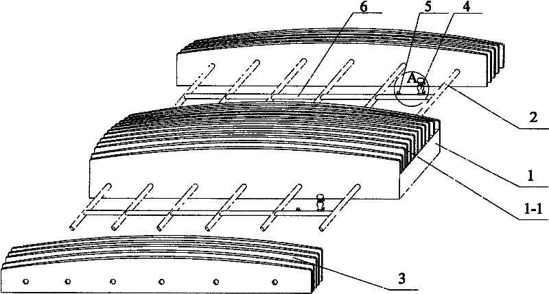
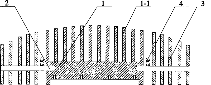
[0015] see figure 1 , a heat pipe cooling device used in high-power LED street lamps, the heat collecting end of the heat pipe 2 in the above device is inserted into the heat conducting base panel 1 where the LED lamp body is positioned in the lamp pool, and a group of separate heat dissipation devices are provided at the heat dissipation end of the heat pipe 2 The fins 3 add a negative pressure adjustment interface communicating with the lumen of the heat pipe 2 and a heat transfer medium replenishment mechanism 4 in the structure of the heat pipe 2 .

[0016] At least two independent heat pipes 2 are arranged in the structure of the above-mentioned heat pipe cooling device.

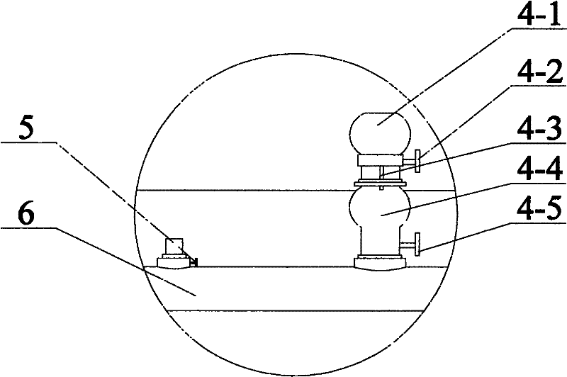
[0017] Connecting pipes 6 connecting the lumens of the heat pipes 2 are added between the independent heat pipes 2, and the negative pressure adjustment interface of the lumens of the heat pipes 2 and the heat transfer medium replenishment mechanism 4 are arranged on the tube walls of the heat pipes 2 ...


PUM


Abstract

The invention discloses a heat pipe radiating device used in a high power LED (light emitting diode) street lamp, which is used for solving the technical problem that the radiating device of the LED street lamp can not dissipate heat normally due to the aging of the heat pipe, an LED lamp body and a circuit board are burnt because of the aggregation of heat at the lamp body. The technical scheme of the invention is as follows: the heat collecting end of a heat pipe in the heat pipe radiating device disclosed by the invention is inserted into a heat conductive base panel, on which the LED lampbody is positioned, in a lamp pool, the radiating end of the heat pipe is provided with a group of independent radiating fins, and a negative adjusting interface and a heat-conducting medium supplement mechanism which are communicated with the cavity of the heat pipe are additionally arranged in the heat pipe structure. Through additionally arranging the negative adjusting interface and the heat-conducting medium supplement mechanism in the heat pipe radiating device, lamp maintenance workers can maintain the heat pipe in the radiating device regularly according to the changes of weather, theproblem that slow heat dissipation of the heat pipe caused by loss of vacuum or heat-conducting medium volatilization is solved, the service life of the street lamp is prolonged, and the constructioncost of the city street lamp is saved greatly.

Description

technical field [0001] The invention relates to a heat pipe cooling device used in high-power LED street lamps, which is applied in the field of urban lighting construction, in particular, it can maintain high-efficiency heat dissipation by adjusting the vacuum degree of the heat pipe and the workload of the heat-conducting medium, thereby prolonging the service life of the lamp. Heat pipe cooling device. Background technique [0002] A heat pipe is a highly efficient enhanced heat transfer element. In 1942, American Gogler proposed the working principle of heat pipes, but it did not attract people's attention. In 1964, due to the needs of aerospace technology, American Grover invented this new type of heat transfer element. According to historical records, until the 1960s, heat pipes generally received people's attention, and gradually stepped out of the laboratory to become a component that improves the efficiency of heat transfer. Before the 1980s, the cost of heat pip...

Claims


Application Information

Patent Timeline
Patent Type & Authority Patents(China)
IPC IPC(8): F21V29/00F21W131/103F21Y101/02F21V29/508F21V29/71
CPCY02B20/72
Inventor 王凯军
Owner 王凯军
Why Eureka
Try Eureka