LED module

a technology of led modules and modules, applied in the direction of semiconductor devices, lighting and heating apparatus, etc., can solve the problems of insufficient design, inability to quickly dissipate heat during the operation, and energy crisis, and achieve the effect of quickly dissipating hea

Inactive Publication Date: 2008-10-30
TAI YUN +1
View PDF4 Cites 35 Cited by
  • Summary
  • Abstract
  • Description
  • Claims
  • Application Information

AI Technical Summary

Benefits of technology

[0014]The present invention has been accomplished under the circumstances in view. It is therefore the main object of the present invention to provide a LED (light emitting diode) module, which dissipates heat quickly during the operation of the LED (light emitting diode). According to one embodiment of the present invention, the LED module comprises a heat sink, which has a top side oxidized to provide an oxidation layer, a top recess formed in the top side beyond the oxidation layer, a groove formed in the top recess and a plurality of mounting through holes cut through the top and bottom sides, a LED mounted in the groove of the heat sink, metal conduction plates fastened to the mounting through holes and extended to the outside of the heat sink, lead wires respectively connected between the metal conduction plates and positive and negative terminals of the LED, a light transmittance resin molded on the groove over the LED, and a lens holder fastened to the heat sink to hold an optical lens over the light transmittance resin. According to another embodiment of the present invention, the LED module comprises a heat sink, the heat sink having a top side oxidized to provide an oxidation layer and a top groove in the top side beyond the oxidation layer; a metal thin film covered on the top groove; at least one light emitting diode respectively fixedly on the metal thin film; a plurality of metal conduction plates affixed to the heat sink; a plurality of lead wires respectively connected between the metal conduction plates and positive and negative terminals of the at last one light emitting diode; and a light transmittance resin molded on the groove of the heat sink and covering the light emitting diode.

Problems solved by technology

In recent decades, human beings consume energy heavily, resulting in an energy crisis.
Because a high brightness LED releases much heat during operation and is enclosed in the package, heat cannot be quickly dissipated during the operation.
However these designs are still not satisfactory in function, having drawbacks as follows:
Similar to conventional designs, this LED packaging design is poor in heat dissipation.
The fabrication of this packaging structure is complicated, resulting in a high cost.
Further, because this packaging structure combines many different materials, the materials may separate from one another easily, causing damage.
However, because the top side of radiator plate is covered by insulating member, radiator plate can only dissipate heat energy through its periphery and bottom side, resulting in low heat dissipation efficiency.
This bonding procedure is difficult to achieve, increasing the cost.
Further, because of high temperature, the bonding interface between radiator plate and insulating member may break easily, causing damage.
Therefore, this structure is less-efficiency in heat dissipation.
Further, the connection interface between the two different materials of metal heat sink and resin package support part may break easily, shortening the service life of the LED.
This design is adapted to improve light projection efficiency with no help to improvement of heat dissipation efficiency.
This design uses materials of low heat dissipation efficiency.
When compared to metal, epoxy resin is inferior in dissipation of heat energy.
To prevent contact between electrode wires of LED chip and metal substrate, the complicated design of circuit board and insulation layer greatly complicates the manufacturing process of the LED lamp and also greatly increases its manufacturing cost.

Method used


Image

  • LED module
  • LED module
  • LED module

Examples


first embodiment

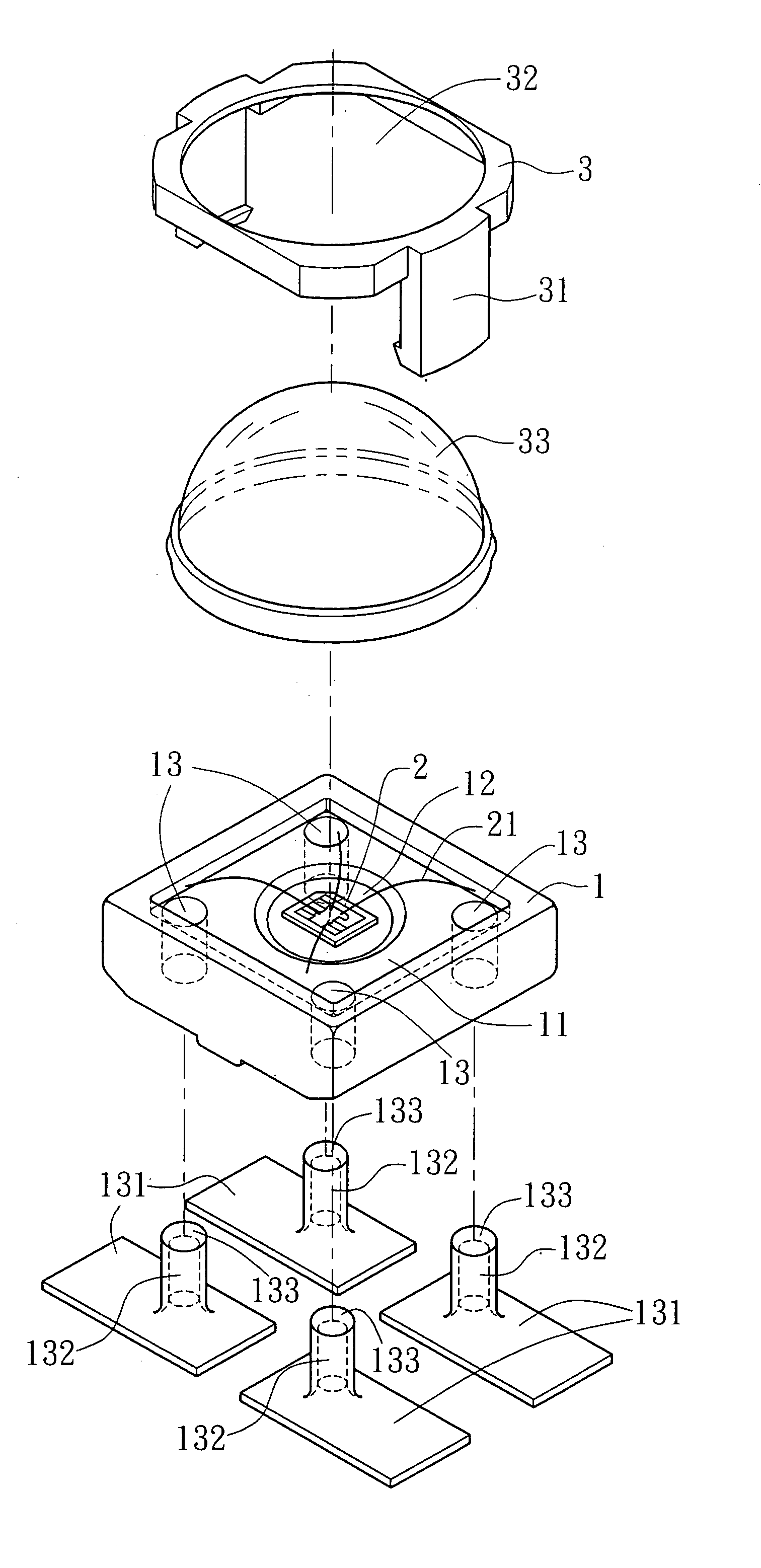
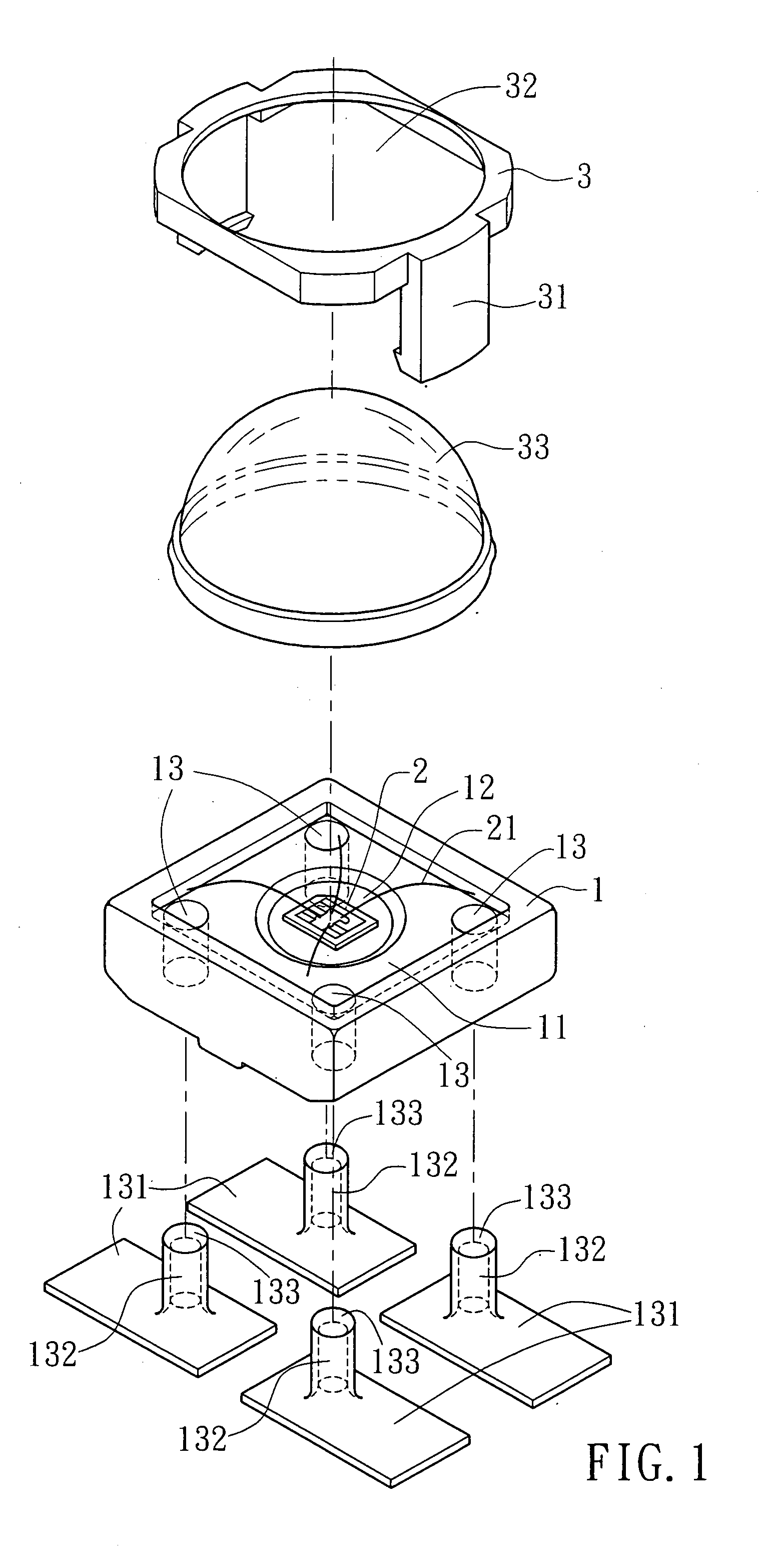
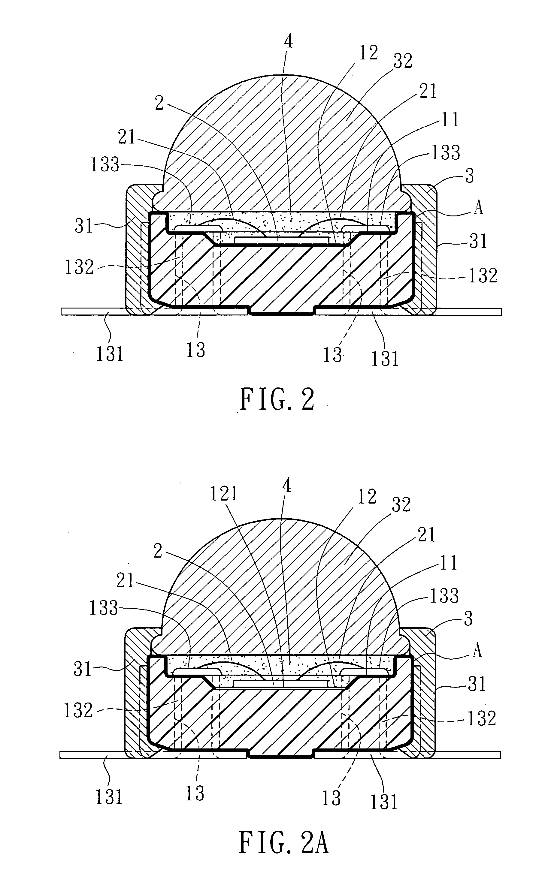
[0025]Referring to FIGS. 1˜3, a LED module in accordance with the present invention is shown comprising a heat sink 1, a LED (Light Emitting Diode) 2 mounted in the heat sink 1, and a lens holder 3 fastened to the heat sink 1 and holding an optical lens 33 corresponding to the LED 2. The heat sink 1 has a top recess 11, a groove 12 formed in the top recess 11 for the mounting of the LED 2, and a plurality of mounting through holes 13 cut through the top and bottom sides. Further, the top surface of the heat sink 1 is covered with an oxidation layer A. Further, a plurality of metal conducting plates 131 are respectively fastened to the heat sink 1. The metal conducting plates 131 each have an upright shank 132 respectively inserted from the bottom side of the heat sink 1 into the mounting through holes 13. After insertion of the upright shanks 132 into the mounting through holes 13, the top ends 133 of the upright shanks 132 are hammered down to affix the upright shanks 132 to the he...

third embodiment

[0027]FIGS. 7˜9 show a LED module in accordance with the present invention. According to this embodiment, the LED module comprises a heat sink 5, a LED (Light Emitting Diode) 2 mounted in the heat sink 5, and a lens holder 3 fastened to the heat sink 5 and holding an optical lens 33 corresponding to the LED 2. The heat sink 5 has a top center recess 52 for the mounting of the LED 2, a plurality of top border recesses 51 spaced around the top center recess 52, an upright rod 511 respectively disposed in each top border recess 51, and a plurality of peripheral bottom notches 53. Further; the top surface of the heat sink 5 is covered with an oxidation layer A. Further, a plurality of metal conducting plates 512 are respectively fastened to the top border recesses 51 of the heat sink 5 and extended to the periphery of the heat sink 5. The metal conducting plates 512 each have a vertical through hole 513 respectively coupled to the upright rod 511. Further, lead wires 21 are respectively...


PUM


Abstract

A LED module includes a heat sink, which is partially oxidized to provide an oxidation layer and has a groove in a top recess thereof, and a plurality of mounting through holes cut through the top and bottom sides, a LED mounted in the groove of the heat sink, metal conduction plates fastened to the mounting through holes and extended to the outside of the heat sink, lead wires respectively connected between the metal conduction plates and positive and negative terminals of the LED, a light transmittance resin molded on the groove over the LED, and a lens holder fastened to the heat sink to hold an optical lens over the light transmittance resin.

Description

REFERENCE TO RELATED APPLICATION[0001]This application is a Continuation-in-Part of patent application Ser. No. 11 / 519,956 filed 13 Sep. 2006, currently pending.BACKGROUND OF THE INVENTION[0002]1. Field of the Invention[0003]The present invention relates to a LED (light emitting diode) and more particularly, to a LED module that dissipates heat quickly during operation.[0004]2. Description of the Related Art[0005]In recent decades, human beings consume energy heavily, resulting in an energy crisis. Nowadays, scientists in different countries are trying hard to develop new energy and every-saving products. In consequence, various petroleum substitutes have been developed, the utilization of solar power has been enhanced, and various low power consumption type. fuel engines and motors and power-saving lighting fixtures have been created. Nowadays; LEDs (light emitting diodes) have been intensively used to substitute for conventional incandescent bulbs and fluorescent bulbs in various ...

Claims


Application Information

Patent Timeline
Patent Type & Authority Applications(United States)
IPC IPC(8): F21V29/00
CPCH01L33/486H01L33/62H01L33/641H01L2224/48091H01L2224/48227H01L2924/01079H01L2924/00014
Inventor TAI, YUNTAI, RUEY-FENG
Owner TAI YUN
Why Eureka
Try Eureka