Thermal interface and method of making the same

a technology of thermal interface and heatsink, which is applied in the direction of cooling/ventilation/heating modification, semiconductor/solid-state device details, semiconductor devices, etc., can solve problems such as voids or spaces, and achieve the effect of rapid removal of heat, improved heat removal efficiency, and improved heat removal efficiency

Inactive Publication Date: 2005-07-21
LARSON RALPH I +1
View PDF13 Cites 36 Cited by
  • Summary
  • Abstract
  • Description
  • Claims
  • Application Information

AI Technical Summary

Benefits of technology

[0017] A heatsink assembly includes a heatsink and a thermal interface disposed on a surface of said heatsink, with the thermal interface including a conductive mesh and a slurry, having the characteristics of a non-eutectic solder joint, impregnated within the conductive mesh. With this particular arrangement, a heat sink which can rapidly remove heat from a heat-generating device provided. The heatsink assembly can correspond to a fan heatsink. In one particular embodiment, the thermally conductive particles are provided as a powder fill which comprises in the range of about 20%-70% by volume of the slurry and the conductive mesh is provided as a conductive wire mesh having in the range of about 25 to about 200 wires per inch with each of the wires having a diameter in the range of about 0.0005 inch to about 0.006 inch. The conductive wire mesh is impregnated with the slurry and the slurry is disposed on each of first and second opposing surfaces of the conductive wire mesh. The mesh / slurry thermal interface fills voids or spaces between the heat-generating device and an applied heatsink. Such voids or spaces can result, for example, from non-linearities in surfaces of the heat sink and / or the heat-generating device. By filling the voids or spaces between the heat generating device and an applied heatsink, the thermal interface improves the amount of heat the heatsink can remove from the heat-generating device. In one embodiment, the slurry comprises a liquid metal alloy of 61% Gallium, 25% Indium, 13% tin and 1% zinc and 40% by volume of silver particles having a size of approximately 25 μm and the conductive mesh is provided as a copper mesh having approximately 100 wires per inch with each of the wires having a diameter of approximately 0.0022 inches.
[0018] An integrated circuit assembly comprising an integrated circuit and a thermal interface disposed on a surface of the integrated circuit, with the thermal interface provided from a conductive mesh and a slurry having the characteristics of a non-eutectic solder joint, impregnated within the conductive mesh. With this particular arrangement, an integrated circuit assembly having a surface through which heat can be rapidly removed is provided. In one particular embodiment, the slurry is provided from a liquid metal alloy and a plurality of thermally conductive particles mixed with said liquid metal alloy. In one embodiment, the thermally conductive particles are provided as a powder fill which comprises in the range of about 20%-70% by volume of the slurry and the conductive mesh is provided as a conductive wire mesh having in the range of about 25 to about 200 wires per inch with each of the wires having a diameter in the range of about 0.0005 inch to about 0.006 inch. The conductive wire mesh is impregnated with the slurry and the slurry is disposed on each of first and second opposing surfaces of the conductive wire mesh. The mesh / slurry thermal interface fills voids or spaces between the heat-generating device and an applied heatsink. Such voids or spaces can result, for example, from non-linearities in surfaces of the heat sink and / or the heat-generating device. By filling the voids or spaces between the heat generating device and an applied heatsink, the thermal interface improves the amount of heat the heatsink can remove from the heat-generating device. In one embodiment, the slurry comprises a liquid metal alloy of 61% Gallium, 25% Indium, 13% tin and 1% zinc and 40% by volume of silver particles having a size of approximately 25 μm and the conductive mesh is provided as a copper mesh having approximately 100 wires per inch with each of the wires having a diameter of approximately 0.0022 inches.

Problems solved by technology

Such voids or spaces can result, for example, from non-linearities in surfaces of the heat sink and / or the heat-generating device.

Method used


Image

  • Thermal interface and method of making the same
  • Thermal interface and method of making the same
  • Thermal interface and method of making the same

Examples


Embodiment Construction

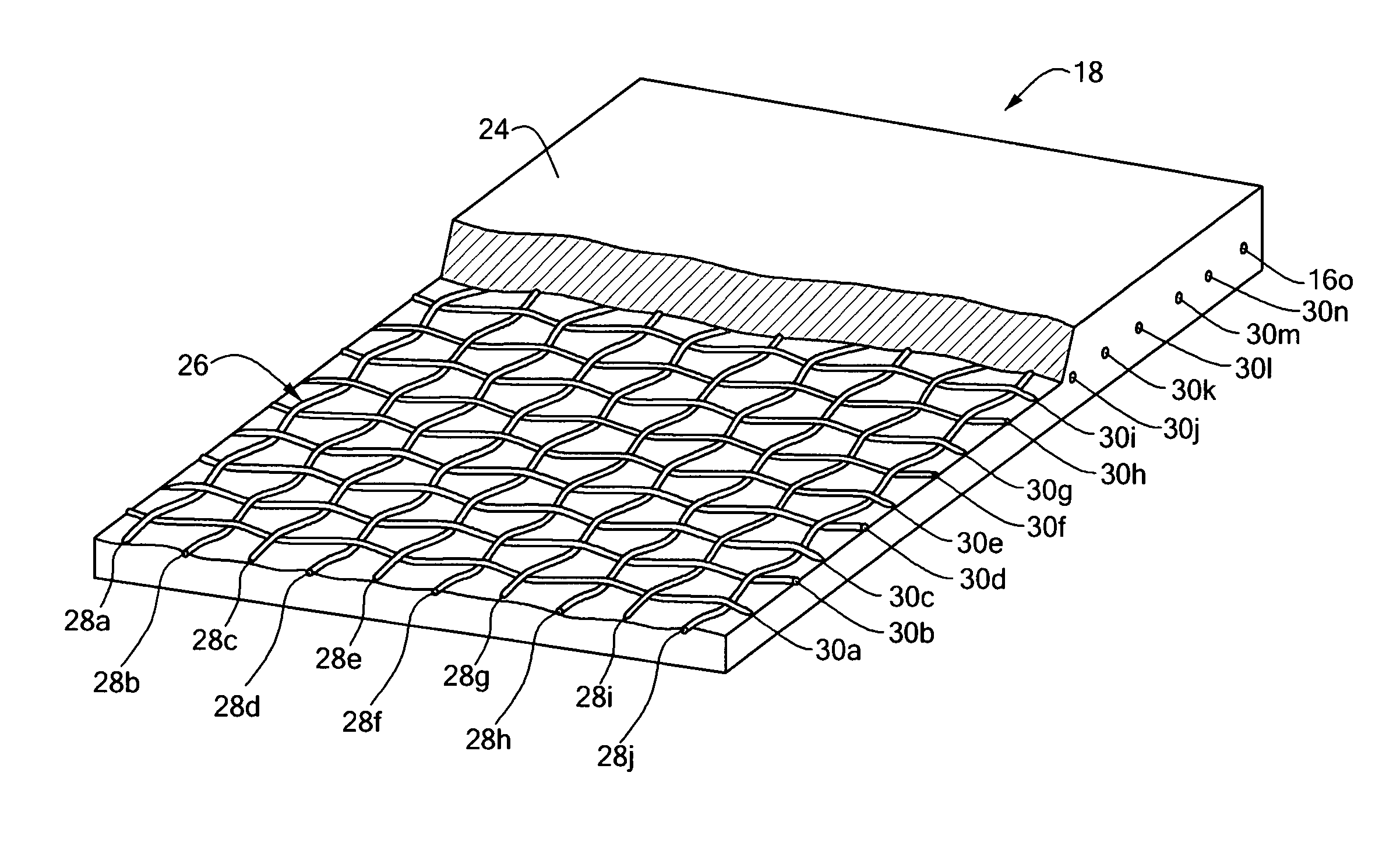
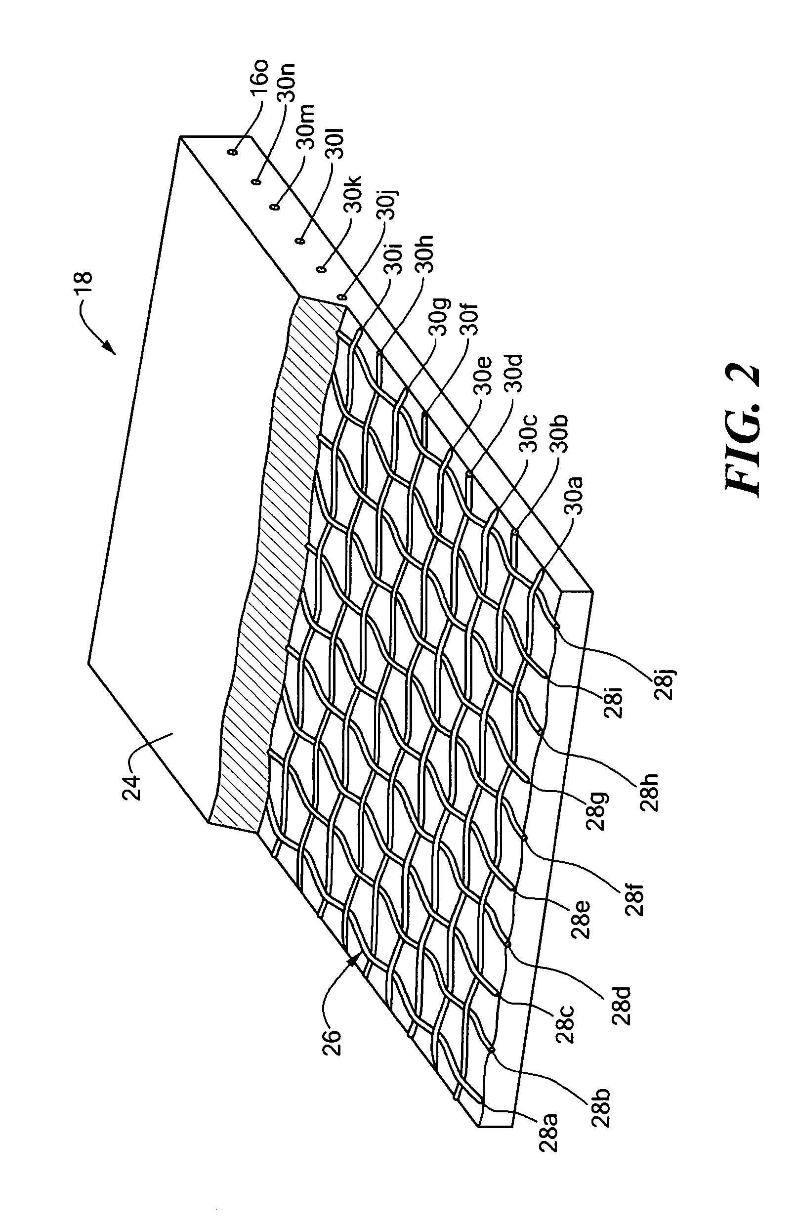
[0027] A thermal interface comprising a mesh impregnated with a slurry of liquid metal and thermally conductive particles is used to provide optimal thermal conductivity between a device such as an integrated circuit (IC) and a heat sink.

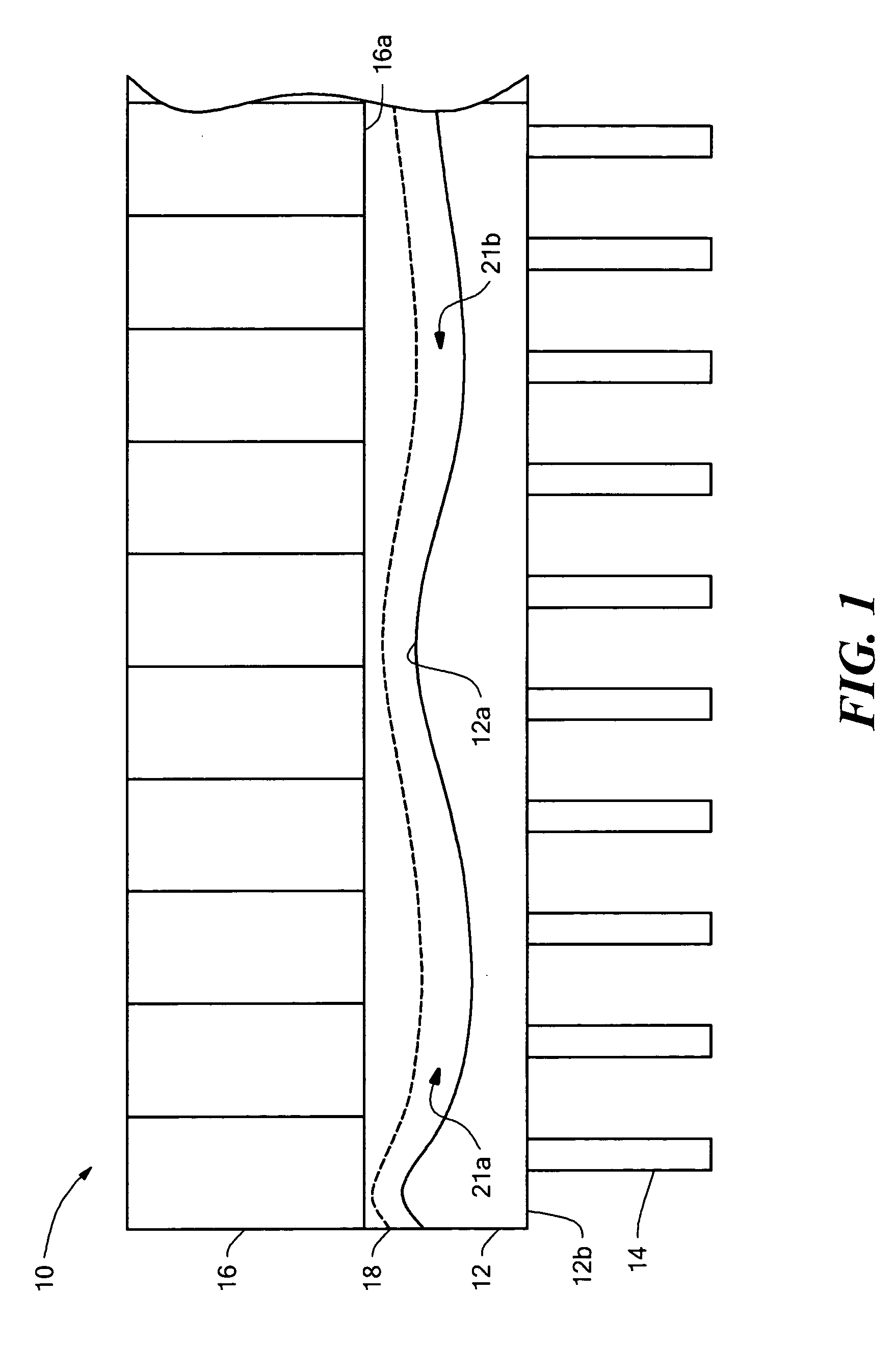
[0028] Referring to FIG. 1 an assembly 10 includes an integrated circuit (IC) or other heat generating device 12 having first and second opposing surfaces 12a, 12b and pins 14 projecting from the surface 12b and a heatsink 16 having a thermal interface 18 disposed between a surface of the heatsink and a surface of the IC. The surface 12a of the IC 12 is non-linear. While the non-linearity here is exaggerated to help illustrate one problem solved by the present invention, even nonlinearity on the order of three thousandths of an inch can be a significant problem when it comes to removing heat from the device 12. It should be appreciated that while only the device 12 is shown having a nonlinear surface, the surface of the heatsink 16 may also be nonl...


PUM

PropertyMeasurementUnit
diameteraaaaaaaaaa
sizeaaaaaaaaaa
melting temperatureaaaaaaaaaa

Abstract

A thermal interface material and methods for preparing the same are disclosed. The thermal interface material comprises a copper mesh and a slurry. The copper mesh is impregnated and coated with the slurry. The slurry comprises a liquid metal alloy mixed with a plurality of thermal conductive particles. The methods include methods for preparing the thermal interface material, preparing the slurry, preparing the mesh, preparing the device for receiving the material, and for applying the thermal interface to the device.

Description

CROSS REFERENCE TO RELATED APPLICATIONS [0001] This application claims the benefit under 35 U.S.C. § 119(e) of U.S. Provisional Application No. 60 / 523,260 filed Nov. 19, 2003; the disclosure of which is hereby incorporated by reference herein in its entirety.STATEMENT REGARDING FEDERALLY SPONSORED RESEARCH [0002] Not applicable. FIELD OF THE INVENTION [0003] The present invention relates generally to a thermal interface and more particularly to a thermal interface between an integrated circuit and a heat sink. BACKGROUND OF THE INVENTION [0004] As is known in the art, there is a trend to reduce the size of semiconductor devices, integrated circuits and microcircuit modules while at the same time having the devices, circuits and modules perform more functions. To achieve this size reduction and increased functionality, it is necessary to include a greater number of active circuits, such as transistors for example, in a given unit area. As a consequence of this increased functionality...

Claims


Application Information

Patent Timeline
Patent Type & Authority Applications(United States)
IPC IPC(8): H01L23/373H01L23/42H05K7/20
CPCH01L23/3733H01L23/3736H01L2924/0002H01L2924/00
Inventor LARSON, RALPH I.PROULX, ROBERT J.
Owner LARSON RALPH I
Why Eureka
Try Eureka