
Time delay switching circuit

A technology for switching circuits and delay relays, applied in circuit devices, electrical components, electronic switches, etc., can solve the problems of component damage of power-saving circuits, short-circuiting of power-saving circuits, and poor delay effect of delay switching circuits. , to achieve the effect of solving the constant flickering of the load and solving the damaged components

Inactive Publication Date: 2011-04-13
东莞市华胜展鸿电子科技有限公司
View PDF6 Cites 0 Cited by
  • Summary
  • Abstract
  • Description
  • Claims
  • Application Information

AI Technical Summary

Problems solved by technology

[0003] However, the delay effect achieved by the existing delay switching circuit is not good
If the delay of some delay switching circuits is too long, it will cause the load to flicker continuously, thus affecting the use of the entire electronic and electrical equipment; A short circuit occurs in the electrical circuit, resulting in damage to the components that constitute the energy-saving circuit

Method used


Image

  • Time delay switching circuit
  • Time delay switching circuit
  • Time delay switching circuit

Examples


Embodiment Construction

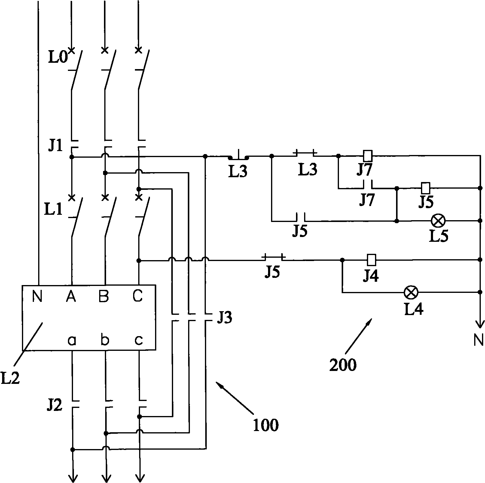
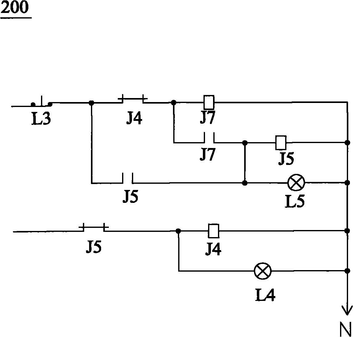
[0015] Embodiments of the present invention will now be described with reference to the drawings, in which like reference numerals represent like elements. As mentioned above, the present invention provides a delay switching circuit, the cooperation between the elements of the delay relay J7 circuit of the delay switching circuit can achieve the effect of delaying 0.1 seconds, thereby solving the problem of the prior art. The short-circuit problem of the devices in the main circuit due to too short time delay also solves the problem in the prior art that the load connected to the circuit flickers continuously due to too long time delay.

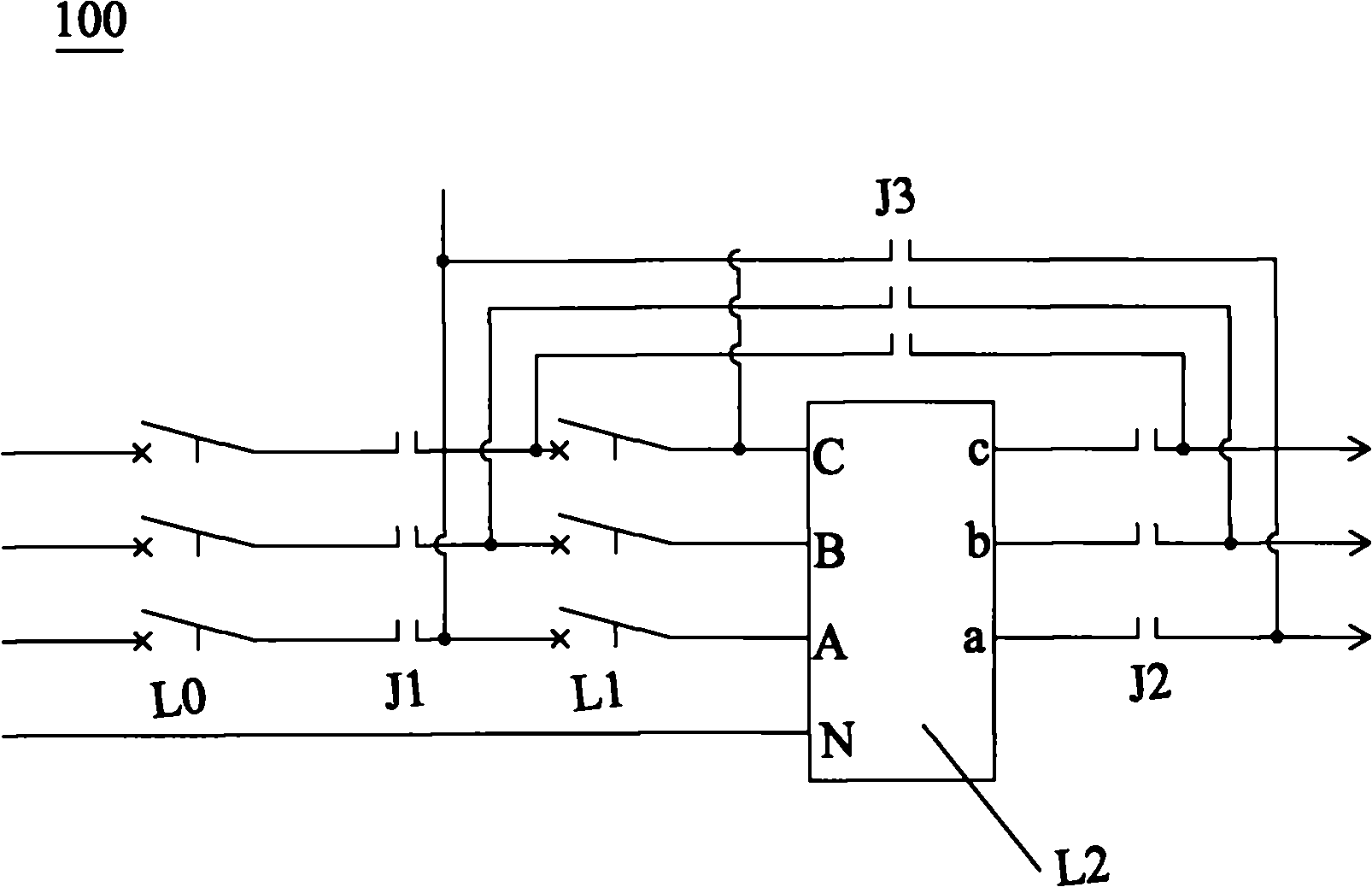
[0016] Please refer to figure 1 and figure 2 , the delay switching circuit includes a main loop 100 and a control loop 200 connected to each other. Such as figure 2 As shown, the main circuit 100 includes a main circuit breaker L0, a main contactor J1, an energy-saving coil protection circuit breaker L1, an energy-saving coil L2, a first...


PUM


Abstract

The invention discloses a time delay switching circuit comprising a main loop and a control loop which are mutually connected, wherein the control loop comprises a time delay relay (J7), the time delay relay (J7) comprises diodes (D1, D2, D3, D4), a triode (T1), resistors (R1, R2), a capacitor (C1) and a voltage-stabilized power supply (V1), the main loop comprises a total breaker (L0), a total contactor (J1), an energy conservation coil protective circuit breaker (L1), an energy conservation coil (L2), a first energy conservation contactor (J2) and a first bypass contactor (J3) which are successively serially connected to each other. Compared with the prior art, in the invention, the matching between all elements of a circuit of the time delay relay (J7) of the time delay switching circuit can achieve the effect of time delay of 0.1 second, thereby solving the problems that devices of the main loop are in short circuit due to excessive short time delay and loads connected with the circuit continuously flicker due to excessive long time delay in the prior art.

Description

technical field [0001] The invention relates to the technical field of time-delay protection of electronic and electrical products, in particular to a time-delay switching circuit. Background technique [0002] The 21st century is an era of severe energy shortage, especially the electric energy that people cannot live without is even more scarce. Therefore, power saving circuits are generally provided in existing electronic and electrical equipment. At the same time, in order to better realize energy saving, a delay switching circuit is also provided. When the power saving circuit fails, the delay switching circuit starts to work so that the load connected to the energy saving circuit and the delay switching circuit can work normally. [0003] However, the delay effect achieved by the existing delay switching circuit is not good. Some delay switching circuits have too long delay, which will cause the load to flicker continuously, thus affecting the use of the entire electr...

Claims


Application Information

Patent Timeline
IPC IPC(8): H02J9/06H03K17/28
Inventor 何运生薛俊钊
Owner 东莞市华胜展鸿电子科技有限公司
Learn More