
Impact absorption member

A technology for absorbing parts and impact force, applied in the direction of elastic shock absorbers, bumpers, etc., can solve the problems of impact energy deviation, inability to guarantee deformation mode, uncertain relationship, etc., and achieve the effect of preventing deviation of absorption performance

Inactive Publication Date: 2013-03-27
丰臣机工株式会社 +1
View PDF1 Cites 0 Cited by
  • Summary
  • Abstract
  • Description
  • Claims
  • Application Information

AI Technical Summary

Problems solved by technology

[0004] However, the impact absorbing member described in the above-mentioned Patent Document 1 does not always have the same deformation mode (for example, the position where bending occurs or the state during deformation) when compressive deformation occurs.
Therefore, even if the impact absorbing part is made into the same shape, there is no guarantee that it will always deform in the same way
The relationship between the compressive load applied to the impact absorbing member and the resulting amount of compressive deformation becomes uncertain, resulting in variations in the absorbed impact energy between products

Method used


Image

  • Impact absorption member
  • Impact absorption member
  • Impact absorption member

Examples


Embodiment Construction

[0024] The technical features of the present invention described above are listed below.

[0025] (Technical Feature 1) The impact absorbing member may have a third body in addition to the first body and the second body. At this time, the third body has a third partial cylinder wall and a pair of third extensions. Wherein, the third part of the cylinder wall constitutes a part of the cylinder wall, that is, a part that cuts out the cylinder wall in the circumferential direction of the cylinder, and a pair of third extensions are formed on the third part of the cylinder wall in the circumferential direction. ends.

[0026] At this time, the second extension part is joined to the first extension part, the third extension part is joined to the second extension part, and the first extension part is joined to the third extension part. The tube is surrounded by the first part of the tube wall, the second part of the tube wall and the third part of the tube wall.

[0027] (Technic...


PUM


Abstract

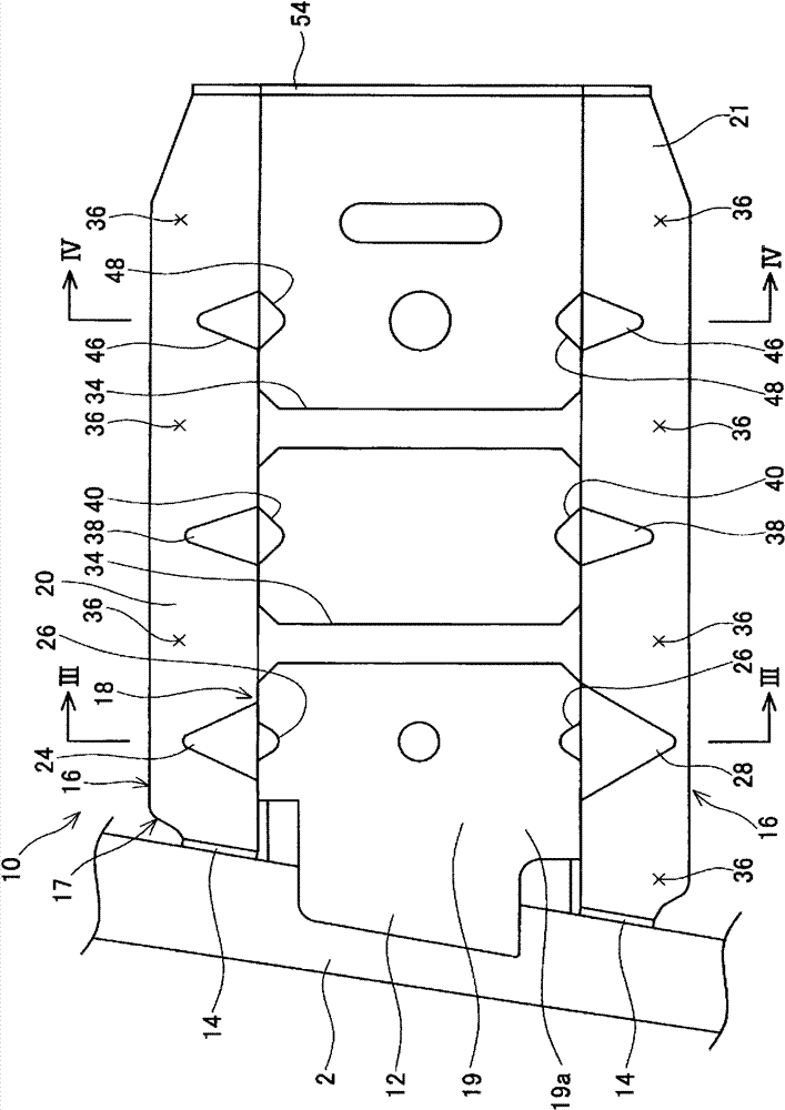
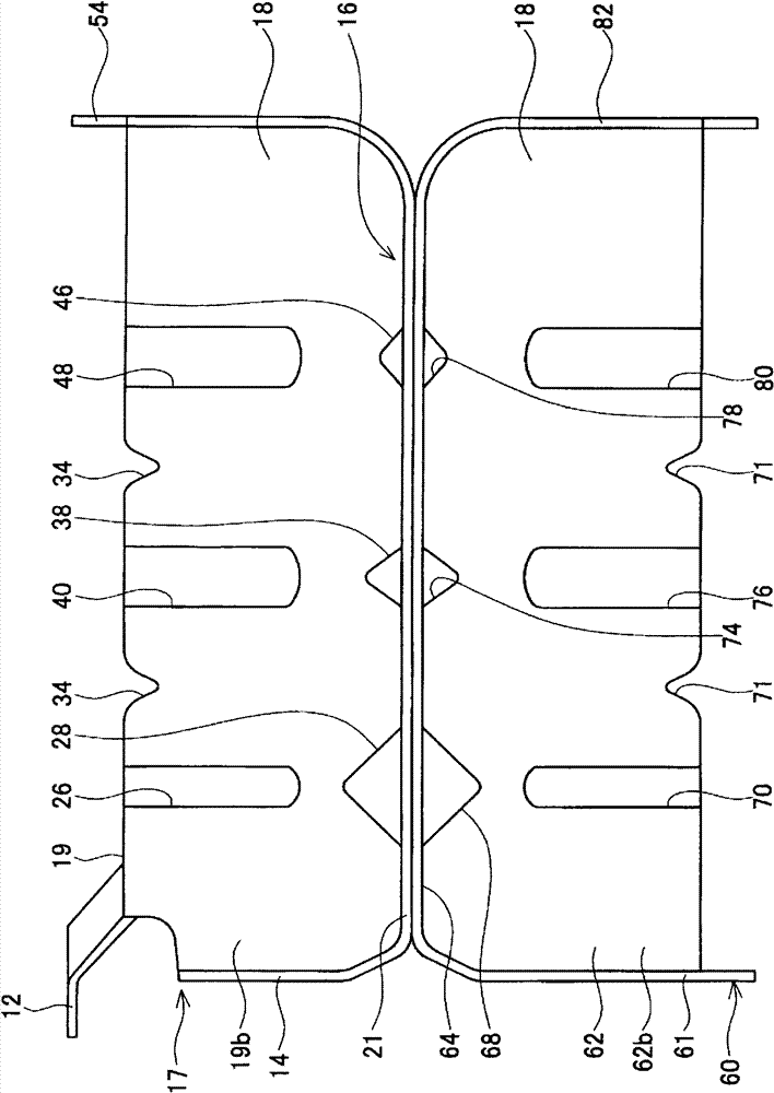
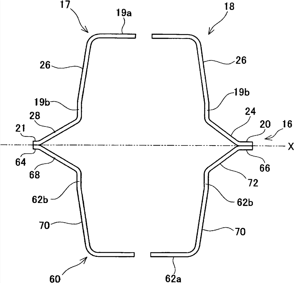
The present application provides a technique, in an impact absorbing member comprising a tube wall and a flange member, for reducing variation in the relationship between a compressive load on the impact absorbing member and the degree of compressive deformation. An impact absorbing member 10 comprises a first main body 17 and a second main body 60. The first main body 17 comprises a first partial tube wall 19 and first flange members 20, 21. The second main body 60 comprises a second partial tube wall 62 and second flange members 64, 66. The first flange member 20 and the second flange member 66 are joined intermittently in an axial direction of the tube. The first flange member 21 and the second flange member 64 are joined intermittently in the axial direction of the tube. A space is formed, in a part of a section where the first flange members 20, 21 and the second flange members 64, 66 are not joined in the axial direction of the tube, between a first partial tube wall 19 side end part of the first flange members 20, 21 and a second partial tube wall 62 side end part of the second flange members 64, 66.

Description

technical field [0001] The present invention relates to an impact force absorbing member mounted on a vehicle, which absorbs impact energy by compressive deformation in the axial direction when the vehicle collides. Background technique [0002] Patent Document 1 discloses an impact absorbing member having a tube wall and an extension portion, wherein the tube is surrounded by the tube wall, and the extension portion extends from the outer peripheral side of the tube wall both toward the outside and toward the axis of the tube. direction extension. When the vehicle collides and the above-mentioned impact absorbing member receives a compressive load in the axial direction, the tube wall and the extension part are bent and deformed, so that the impact absorbing member compresses and deforms in the axial direction. The impact absorbing member has a first body and a second body. The 1st main body and the 2nd main body respectively have part cylinder wall and extension part, an...

Claims


Application Information

Patent Timeline
Patent Type & Authority Patents(China)
IPC IPC(8): B60R19/34F16F7/12
CPCF16F7/12B60R19/34
Inventor 金谷隆邦出水博之程谷幸平
Owner 丰臣机工株式会社
Learn More