Supercharge Your Innovation With Domain-Expert AI Agents!

Control method of electronic brake

一种电子制动、控制方法的技术,应用在制动器、制动作用启动装置、车辆部件等方向,能够解决难以获得ABS控制响应性能等问题

Active Publication Date: 2011-04-20
HL MANDO CORP
View PDF5 Cites 3 Cited by
  • Summary
  • Abstract
  • Description
  • Claims
  • Application Information

AI Technical Summary

Problems solved by technology

Therefore, the conventional motor position control method is difficult to obtain excellent ABS control response performance

Method used


Image

  • Control method of electronic brake
  • Control method of electronic brake
  • Control method of electronic brake

Examples


Embodiment Construction

[0017] Now, embodiments of the present invention will be described in detail, examples of which are illustrated in the accompanying drawings, in which like reference numerals refer to like parts throughout.

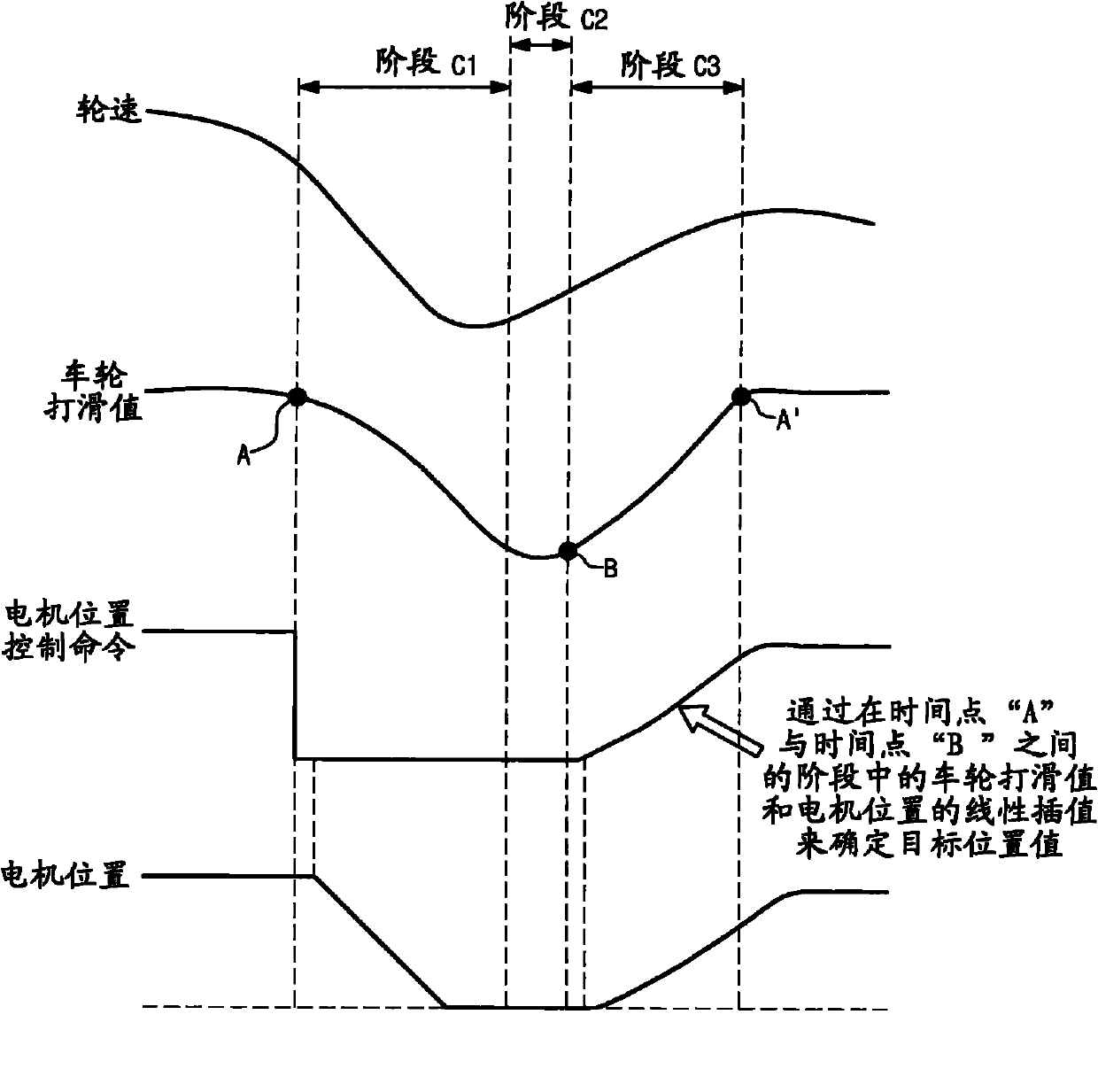
[0018] figure 1 It is a control block diagram illustrating an anti-lock braking system (ABS) of electronic braking according to an embodiment of the present invention.

[0019] exist figure 1 Among them, the electronic brake ABS control system according to the embodiment of the present invention includes a brake pedal position sensor 10 , a wheel speed sensor 20 , an electronic brake control unit 30 , a motor 40 and a motor position sensor 70 .

[0020] The brake pedal position sensor 10 is used to sense the driver's pedaling force applied to the brake pedal (ie, the position of the brake pedal), and transmit the sensed signal to the electronic brake control unit 30 .

[0021] The wheel speed sensor 20 is provided at each of the wheels FL, RR, RL, and FR, and serves to ...


PUM


Abstract

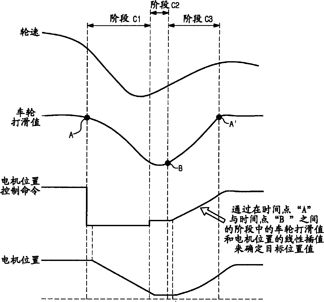
Disclosed herein is a method of controlling an Anti-lock Brake system (ABS) of an electronic brake, which is driven using an electric motor. In ABS braking in which braking and braking-release motions are repeated according to a wheel slip value, the electric motor is controlled in a re-braking section to link a position of a brake pad with a change in wheel speed, to enhance ABS control responsiveness and to reduce stopping distance with maximized brake force.

Description

technical field [0001] Embodiments of the present invention relate to a method of controlling an anti-lock braking system (ABS) using electric braking driven by a motor. Background technique [0002] Electronic braking, driven by an electric motor, is used to slow or stop a vehicle, or to hold a vehicle stationary. Such electronic braking conventionally generates braking force by using brake pads to strongly squeeze opposite sides of a brake disc that rotates with the wheel. [0003] When utilizing such electronic braking to perform anti-lock braking system (ABS) braking that repeats the braking action and brake release action in rapid cycles, it may be necessary to keep the vehicle's wheel slip values ​​as close to the minimum as possible. optimal zone for vehicle stability and reduced parking coast distance. The purpose of keeping the wheel slip values ​​of the vehicle in a region as close to optimum as possible is to reduce variations in the wheel slip values. For this...

Claims


Application Information

Patent Timeline
Patent Type & Authority Applications(China)
IPC IPC(8): B60T8/176B60T8/32
CPCB60T7/042B60T13/741B60T13/746B60T8/17616B60T8/00B60T8/1764B60W40/06
Inventor 金明俊
Owner HL MANDO CORP
Features
  • R&D
  • Intellectual Property
  • Life Sciences
  • Materials
  • Tech Scout
  • Unparalleled Data Quality
  • Higher Quality Content
  • 60% Fewer Hallucinations
Learn More