Spring operation mechanism

A technology of operating mechanism and return spring, which is applied in the direction of contact drive mechanism and power device inside the switch, etc. It can solve the problems of uncompact structure, no labor-saving mechanism, and large size of spring operating mechanism.

Inactive Publication Date: 2011-04-20
SUNRISE GRP CO LTD
View PDF6 Cites 5 Cited by
  • Summary
  • Abstract
  • Description
  • Claims
  • Application Information

AI Technical Summary

Problems solved by technology

[0002] The utility patent with the authorized notification number CN201041775Y discloses a spring operating mechanism, which installs a transmission system between the frames, and the transmission system is composed of cams, rollers and a four-stage four-bar linkage connected by pivot pins. The core of the design lies in, Through the optimization of the size parameter design of each component, only the first-stage four-bar linkage is used to realize the function of the spring operating mechanism. Although the structure of the spring operating mechanism is simple, its structure itself does not have a labor-saving mechanism, mainly relying on the energy storage spring, and The cam and each power arm in the first-stage four-linkage drive the moving contact. That is to say, the above structure ensures the switch by increasing the elastic stiffness of the energy storage spring and lengthening the cam and each power arm in the first-stage four-linkage. The design requirements of the energy storage spring, and the increase in the elastic stiffness of the energy storage spring, as well as the lengthening of each power arm in the cam and the first-stage four-link, determine that the active force used to drive the energy storage spring to store energy is relatively large, and the energy storage spring , cams, first-stage four-links, and other related parts (such as the frame used to install the rack) are all required to be larger in size or the materials used to manufacture the above parts have higher requirements
Therefore, the size of the above-mentioned spring operating mechanism is too large, and the structure is not compact

Method used


Image

  • Spring operation mechanism
  • Spring operation mechanism
  • Spring operation mechanism

Examples


Embodiment Construction

[0015] The present invention will be further described below in conjunction with accompanying drawing.

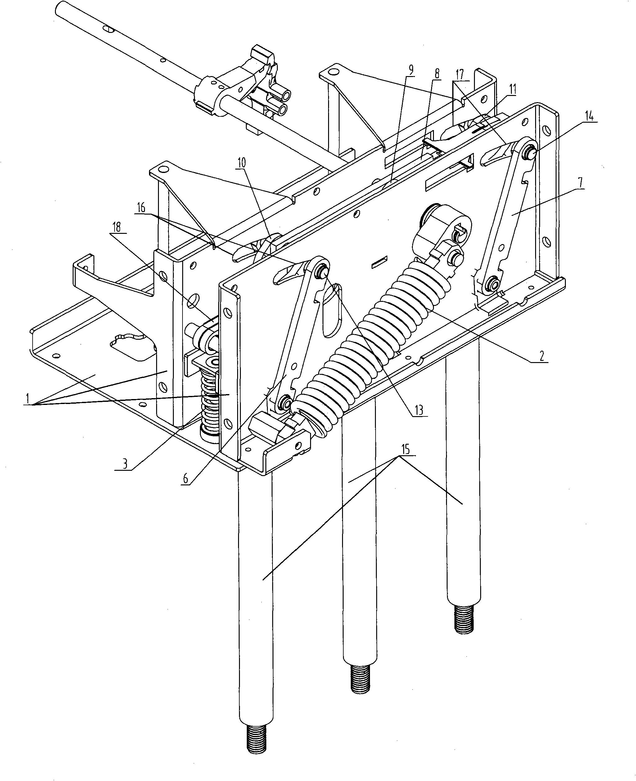
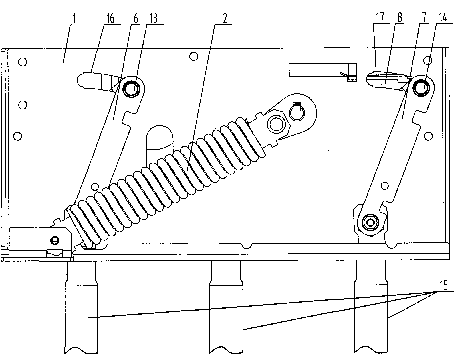
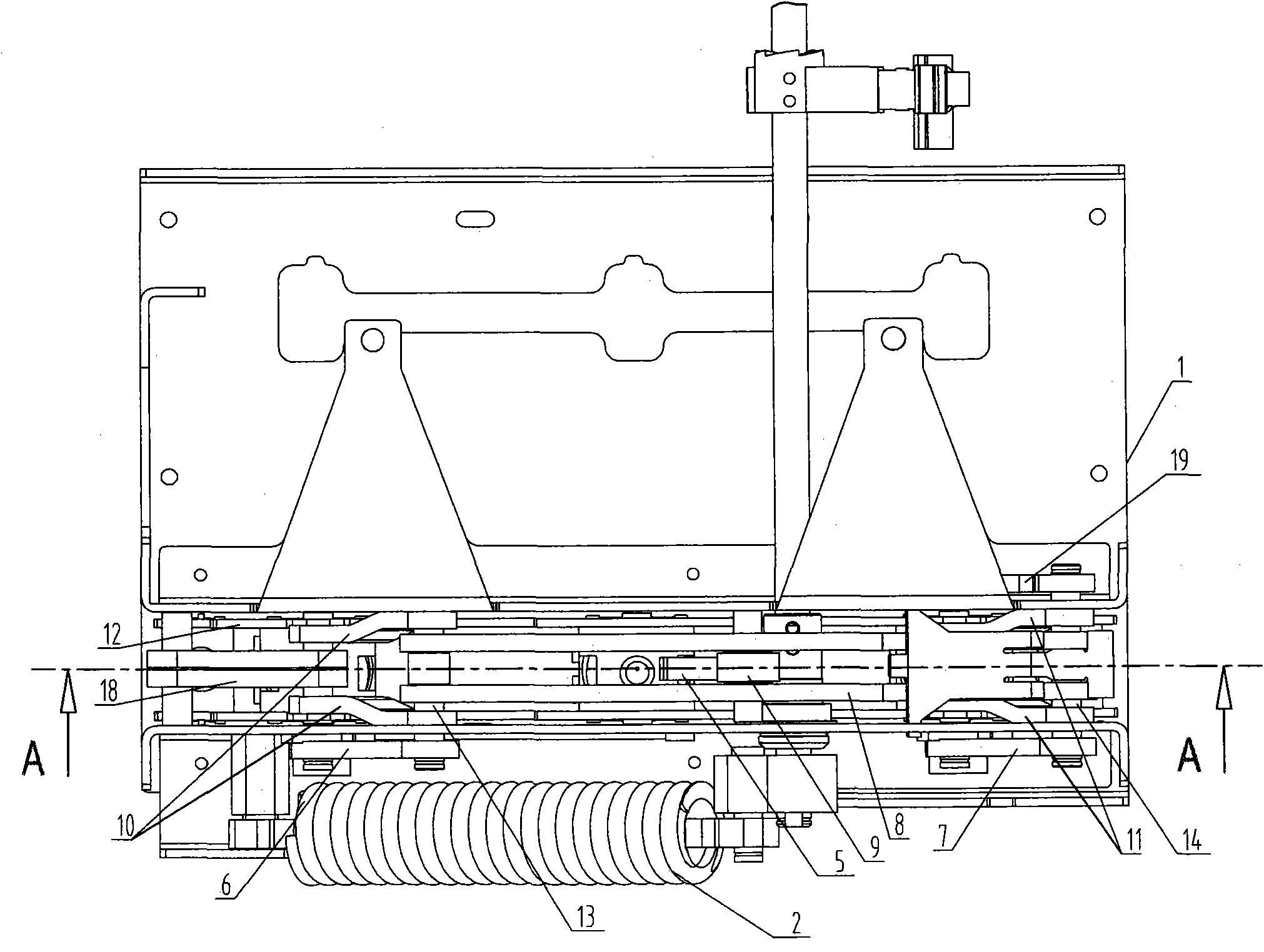
[0016] The spring operating mechanism of the present invention includes a mounting frame 1 as a frame, an energy storage spring 2, a return spring 3, a movable contact spring 4, a cam 5 and a parallelogram, and the parallelogram includes a first frame rod 6 , the second rack rod 7 and the first connecting rod 8, the first connecting rod 8 is equipped with a roller 9, the roller 9 is against or away from the cam 5, and it also includes a connecting rod that can be used to form a joint with the first rack rod 6 The second connecting rod 10 in the rod extreme position state, the third connecting rod 11 that can be used to form the connecting rod extreme position state with the second frame rod 7, the support frame driven by the second connecting rod 10 and the third connecting rod 11 12; the second connecting rod 10 and the third connecting rod 11 are equal in length and paral...


PUM


Abstract

The invention discloses a spring operation mechanism which is labor-saving, small in size and compact in structure. The spring operation mechanism comprises an installation frame as a rack, an energy storage spring, a returning spring, a moving contact spring, a cam and a parallel four-bar linkage, wherein the parallel four-bar linkage comprises a first rack rod, a second rack rod, a first connecting rod, a second connecting rod which can be used for forming a connecting-rod limit state with the first rack rod, a third connecting rod which can be used for forming a connecting-rod limit state with the second rack rod, and a support bracket; the lengths of the second connecting rod and the third connecting rod are equal, and the second connecting rod and the third connecting rod are arranged in parallel to each other; one end of the second connecting rod, one end of the first rack rod and one end of the first connecting rod are all hinged to a first point; and one end of the third connecting rod, one end of the second rack rod and one end of the first connecting rod are all hinged to a second point, and the other end of the second connecting rod and the other end of the third connecting rod are hinged with the support bracket.

Description

technical field [0001] The invention relates to the technical field of electric equipment, in particular to a spring operating mechanism. Background technique [0002] The utility patent with the authorized notification number CN201041775Y discloses a spring operating mechanism, which installs a transmission system between the frames, and the transmission system is composed of cams, rollers and a four-stage four-bar linkage connected by pivot pins. The core of the design lies in, Through the optimization of the size parameter design of each component, only the first-stage four-bar linkage is used to realize the function of the spring operating mechanism. Although the structure of the spring operating mechanism is simple, its structure itself does not have a labor-saving mechanism, mainly relying on the energy storage spring, and The cam and each power arm in the first-stage four-linkage drive the moving contact. That is to say, the above structure ensures the switch by incre...

Claims


Application Information

Patent Timeline
Patent Type & Authority Applications(China)
IPC IPC(8): H01H3/30H01H3/42H01H3/46
Inventor 潘永成黄保富樊建荣
Owner SUNRISE GRP CO LTD
Why Eureka
Try Eureka