Efficiency monitoring of a compressor

A compressor and efficiency technology, which is applied in the field of compressor efficiency monitoring, can solve the problems of limited estimated accuracy and working parameters, etc.

Inactive Publication Date: 2011-04-20
SIEMENS AG
View PDF11 Cites 7 Cited by
  • Summary
  • Abstract
  • Description
  • Claims
  • Application Information

AI Technical Summary

Problems solved by technology

The above two methods respectively allow only a rough estimation of the efficiency loss, since the precision of the estimation is strongly limited especially due to the multidimensionality of the operating parameters
[0010] The determination of the efficiency loss in general is therefore particularly problematic, since the efficiency is always a function of the operating point, which is determined by several influencing variables of a multidimensional parameter family and the variation must always refer to the same operating conditions in order to be able to achieve the required accuracy draw conclusions

Method used


Image

  • Efficiency monitoring of a compressor
  • Efficiency monitoring of a compressor
  • Efficiency monitoring of a compressor

Examples


Embodiment Construction

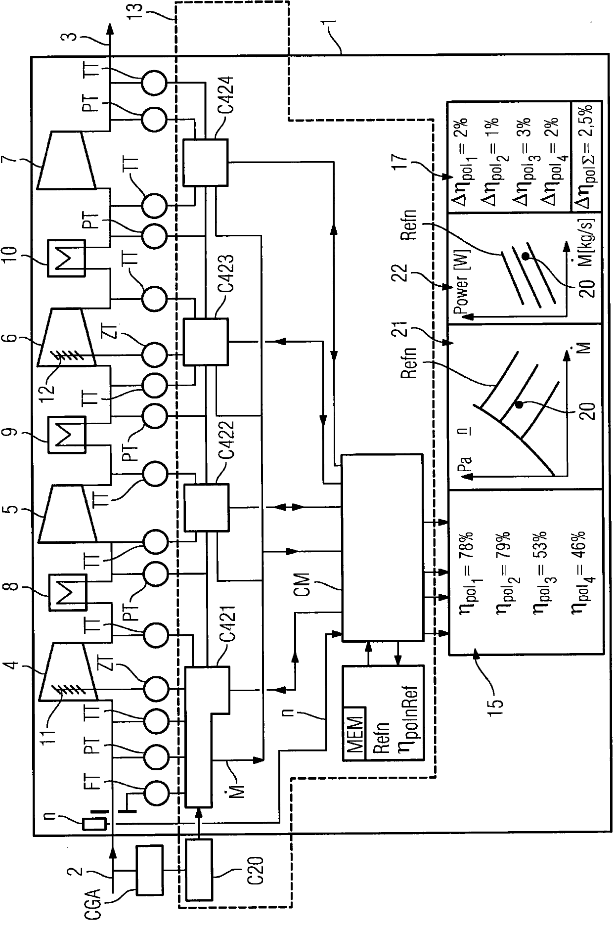
[0032] figure 1 A compressor 1 is shown schematically, on which the method according to the invention for monitoring the efficiency is to be applied. Mass flow in compressor 1 (measured as ) enters as incoming mass flow 2 and exits as outgoing mass flow 3 . The compressor 1 has four stages 4, 5, 6, 7 (from left to right respectively the first stage 4 to the fourth stage 7), through which the incoming mass flow 2 flows, wherein intercooling is provided in each case between the stages Devices 8, 9, 10 (Necessary corrections shall be made to the numbering method).

[0033] Before entering each stage 4 , 5 , 6 , 7 and after exiting each stage 4 , 5 , 6 , 7 the pressure is measured by means of the pressure measuring point PT and the temperature is measured by means of the temperature measuring point TT. Because apart from a small and understandable pressure loss in the intercooler 8 , 9 , 10 , the pressure before the intercooler 8 , 9 , 10 and the pressure after the intercooler...


PUM


Abstract

The invention relates to a method for monitoring the efficiency (Eta pol n) of a compressor (1), in which a mass flow, an entry pressure (Pe n), an exit pressure (Pa n), an entry temperature (Te n), an exit temperature (Ta n) of the process medium are determined and a performance factor is ascertained. In order to improve the accuracy it is suggested that - at the inlet of each stage (4, 5, 6, 7), a stage entry temperature (Ten) and a stage entry pressure (Pen) are directly or indirectly measured as measurement parameters, - at the outlet of each stage, a stage exit temperature (Tan) and a stage exit pressure (Pan) are directly or indirectly measured as measurement parameters, and each stage (4, 5, 6, 7) is assigned a module (C421 to C424) which calculates a stage efficiency (Eta pol n), for example as polytropic stage efficiency, as performance factor from the measurement parameters using the calculation means.

Description

technical field [0001] The invention relates to a method for monitoring the efficiency of a compressor of at least two stages when compressing a process medium, wherein as a parameter the [0002] - flow through the compressor, [0003] - the inlet pressure of the sucked process medium, [0004] - the discharge pressure of the compressed process medium, [0005] - the entry temperature of the sucked process medium, [0006] - Discharge temperature of the compressed process medium [0007] And the power coefficient is calculated from said parameters by means of a calculation device. Background technique [0008] The monitoring of turbocompressors in operation currently basically includes these variables: shaft vibration and position, bearing temperature and other variables, the state of components or system parts being able to be deduced from individual measurements. With regard to the economical operation of the compressor, it is of particular interest at what efficienc...

Claims


Application Information

Patent Timeline
Patent Type & Authority Applications(China)
IPC IPC(8): G01M15/14F04D27/00
CPCG01M15/14F04D27/001
Inventor G·温克斯A·尼泽
Owner SIEMENS AG
Why Eureka
Try Eureka