Device for measuring transverse stress of pipeline

A transverse stress and stress measurement technology, applied in measurement devices, force/torque/work measuring instruments, and measurement of properties using piezoelectric devices, etc. And effective detection and other problems, to achieve the effect of accurate measurement, high measurement efficiency, and reduce the interference of equipment to the original stress

Inactive Publication Date: 2017-11-21
康殷滔
View PDF5 Cites 2 Cited by
  • Summary
  • Abstract
  • Description
  • Claims
  • Application Information

AI Technical Summary

Problems solved by technology

[0007] The technical problem to be solved by the present invention is that the existing detection equipment cannot quickly and effectively detect the lateral stress of the pipeline, which will shorten the service life of the pipeline and cause accidents in severe cases. The device is specially used to measure the lateral stress of the pipeline, which is easy to use and accurate in detection, ensuring the safety of the pipeline

Method used


Image

  • Device for measuring transverse stress of pipeline
  • Device for measuring transverse stress of pipeline

Examples


Embodiment 1

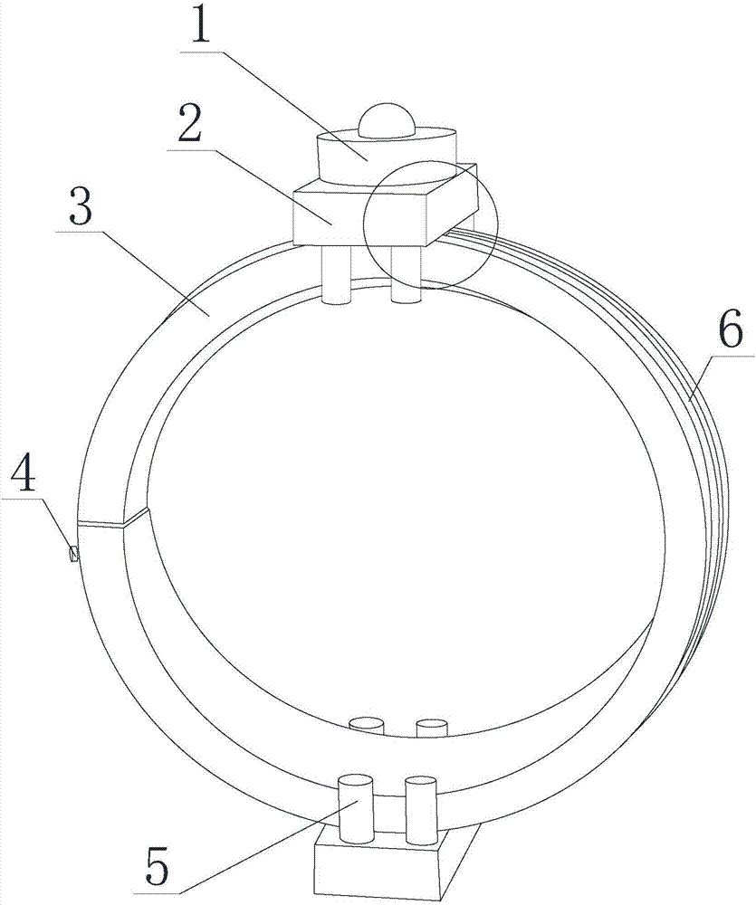
[0021] Such as figure 1 , figure 2 As shown, the device based on the measurement of the lateral stress of the pipeline includes a fixing strip 3 for fastening in the radial direction of the pipeline. The two ends of the fixing strip 3 have different sizes, and the larger end is open and has a cavity, and can Ensure that the smaller end can be inserted into the cavity of the larger end to form a ring structure, and change the insertion depth of the end of the fixing strip 3 according to the diameter of the pipeline at the measurement point, and then change the diameter of the ring structure, so that the fixing strip 3 It can form full contact with the outer wall of the pipeline, realize the firmness of the fixation, and ensure the accuracy of the measurement without moving during the measurement. Two sets of stress measurement devices 1 are installed on the fixing bar 3, which are symmetrical along the center of the pipeline during use. The stress measurement device 1 can mov...

Embodiment 2

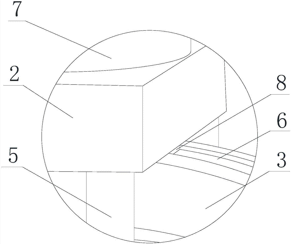
[0023] Such as figure 1 , figure 2 As shown, on the basis of Embodiment 1, the outer wall of the ring structure formed by the fixing bar 3 is concavely formed to form a mounting groove 6 , and the stress measuring device 1 is inserted into the mounting groove 6 and can move along the mounting groove 6 . The stress measurement device 1 includes a mounting plate 2, several measuring heads 5 are arranged below the mounting plate 2, the fixing strip 3 is arranged between the areas formed by the measuring heads 5, and the axes of the measuring heads 5 pass through the center of the ring structure, and the mounting plate 2 A guide block 8 is provided toward one end of the fixing bar 3. The guide block 8 is inserted into the installation groove 6 and can move along the installation groove 6. In order to ensure the firmness of the stress measurement device 1 and the convenience of movement, the guide block 8 and the mounting groove 6 should form a structure that matches each other. ...

Embodiment 3

[0027] Such as figure 1 , figure 2 As shown, on the basis of the above embodiment, the outer wall of the fixing bar 3 is equipped with locking pins 4, and when the fixing bar 3 forms a ring structure, the locking pins 4 are inserted into the outer walls of both ends of the fixing bar 3 at the same time. In order to prevent interference in the structure, the locking position of the locking pin 4 needs to be strictly designed. At the outer wall of the end with a larger size, the locking pin 4 should be inserted from close to the end and interact with the installation groove 6. No interference, no interference with the movement of the stress measuring device 1 on the fixing bar 3, so that the stress measuring device 1 can complete the measurement of all points of the ring structure on the pipeline, and the direction of the locking pin 4 inserted into the fixing bar 3 is towards the pipeline In this way, it is firm and not easy to fall off when fixed, so that after the position ...


PUM


Abstract

The invention discloses a device for measuring the transverse stress of a pipeline. The device comprises a fixed strip which is buckled in the radial direction of the pipeline. One end of the fixed strip is inserted into another end, so an annular structure is formed. The diameter of the annular structure is changed along with the change of the insertion depth of the end of the fixed strip. Multiple groups of stress measurement devices are installed on the fixed strip and are capable of moving along the outer wall of the fixed strip. According to the invention, the device is simple in structure, convenient to use and high in measurement efficiency; precise measurement of transverse stress of the pipeline can be achieved; interference to original stress by the device in the measurement process is reduced; precise reference data is provided for judgment of conditions of the pipeline; and use safety of the pipeline is ensured.

Description

technical field [0001] The invention relates to a tool for measuring pipeline stress in a laboratory, in particular to a device based on measuring pipeline transverse stress. Background technique [0002] A pipeline is a device used to transport gas, liquid or fluid with solid particles connected by pipes, pipe connectors and valves. Usually, after the fluid is pressurized by blowers, compressors, pumps and boilers, it flows from the high-pressure part of the pipeline to the low-pressure part, and it can also be transported by the pressure or gravity of the fluid itself. Pipes are widely used, mainly in water supply, drainage, heat supply, gas supply, long-distance transportation of oil and natural gas, agricultural irrigation, hydraulic engineering and various industrial devices. [0003] The pipeline may be subjected to many kinds of external forces, including its own weight (the weight of the pipe, valve, pipe coupling, insulation layer and fluid in the pipe), the pressu...

Claims


Application Information

Patent Timeline
IPC IPC(8): G01L1/16G01L1/02G01L5/00
CPCG01L1/02G01L1/16G01L5/00
Inventor 康殷滔
Owner 康殷滔
Why Eureka
Try Eureka