Rod holder and minimally invasive spine surgery system using the same

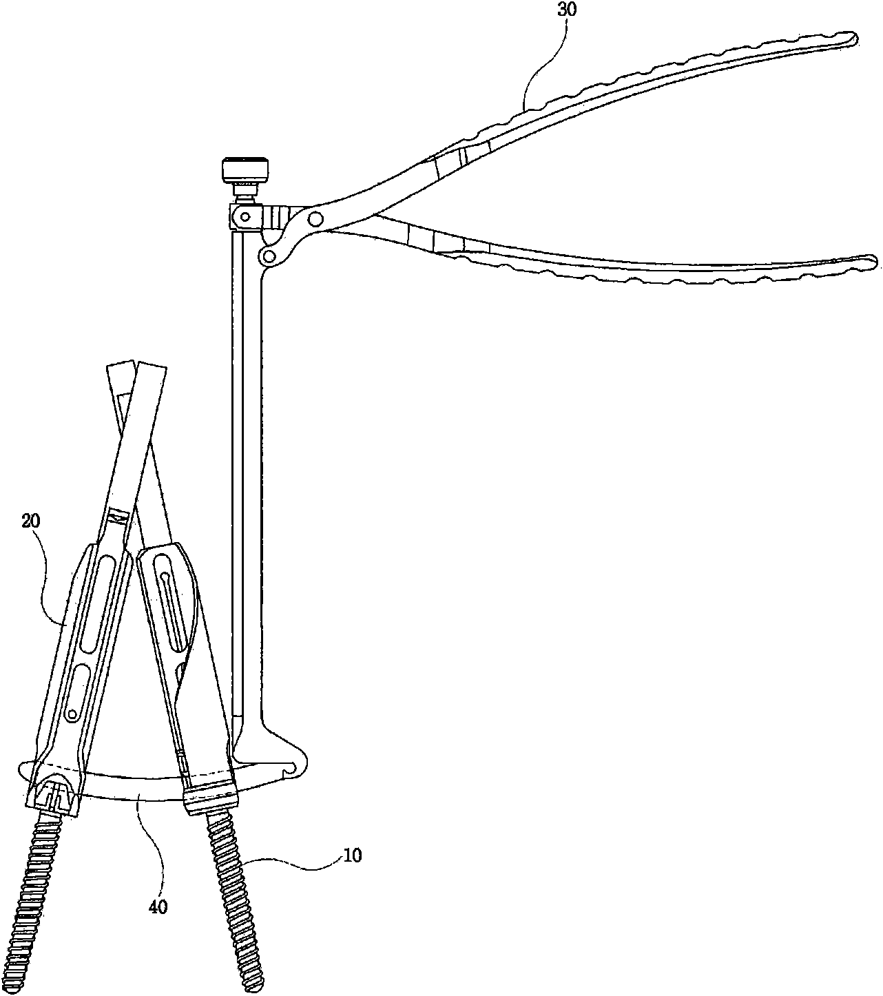
A technique of minimally invasive surgery and a holder, which is applied in the direction of surgery, fixers, internal fixers, etc., and can solve the problem of peripheral tissue or nerve damage, difficulty in accurately controlling the insertion direction of the rod 40, installation of the rod 40, and injury to the patient, etc. problems, to achieve the effects of less damage to peripheral nerves and tissues, shortened spinal surgery time, and easy operation

Inactive Publication Date: 2011-04-27
GS MEDICAL CO LTD
View PDF3 Cites 12 Cited by
  • Summary
  • Abstract
  • Description
  • Claims
  • Application Information

AI Technical Summary

Problems solved by technology

[0011] However, in this method, when the doctor grasps the rod holder 30 and inserts the rod 40 into the surgical site, it is necessary to insert the rod holder into the patient while grasping the handle of the rod holder 30. In vivo, there are problems that hinder concentration on two manipulations (i.e., grasping and insertion) at the same time
Therefore, if the doctor loosens the grasping operation due to inattention before installing the rod, there is a risk that the surgical site will be enlarged to find the rod, and the minimally invasive surgery method loses its meaning
[0012] In addition, in this method, when the doctor grasps the rod holder 30 and inserts the rod 40 into the surgical site, the holding assembly 20 connected to the rod pedicle screw 10 swings or the doctor's posture In the case of shaking, it is difficult to install the rod 40 on the pedicle screw 10 due to the difficulty in accurately controlling the insertion direction of the rod 40, thereby causing damage to surrounding tissues or nerves during the insertion of the rod 40 or injury and there is a problem of causing great pain to the patient after surgery

Method used


Image

  • Rod holder and minimally invasive spine surgery system using the same
  • Rod holder and minimally invasive spine surgery system using the same
  • Rod holder and minimally invasive spine surgery system using the same

Examples


Embodiment Construction

[0056] Hereinafter, preferred embodiments of the present invention will be described in detail with reference to the accompanying drawings. When describing the embodiments of the present invention, since the detailed descriptions of introduced related known functions or structures may obscure the gist of the present invention, their detailed descriptions are omitted.

[0057] Before describing the embodiment of the present invention, the position of the rod holder is used as a reference below, the spine side as the surgical site is defined as the "front" direction, and the operator's side is defined as the "rear" direction. Similarly, the The movement toward the spine was defined as "forward", and the movement toward the operator was defined as "backward".

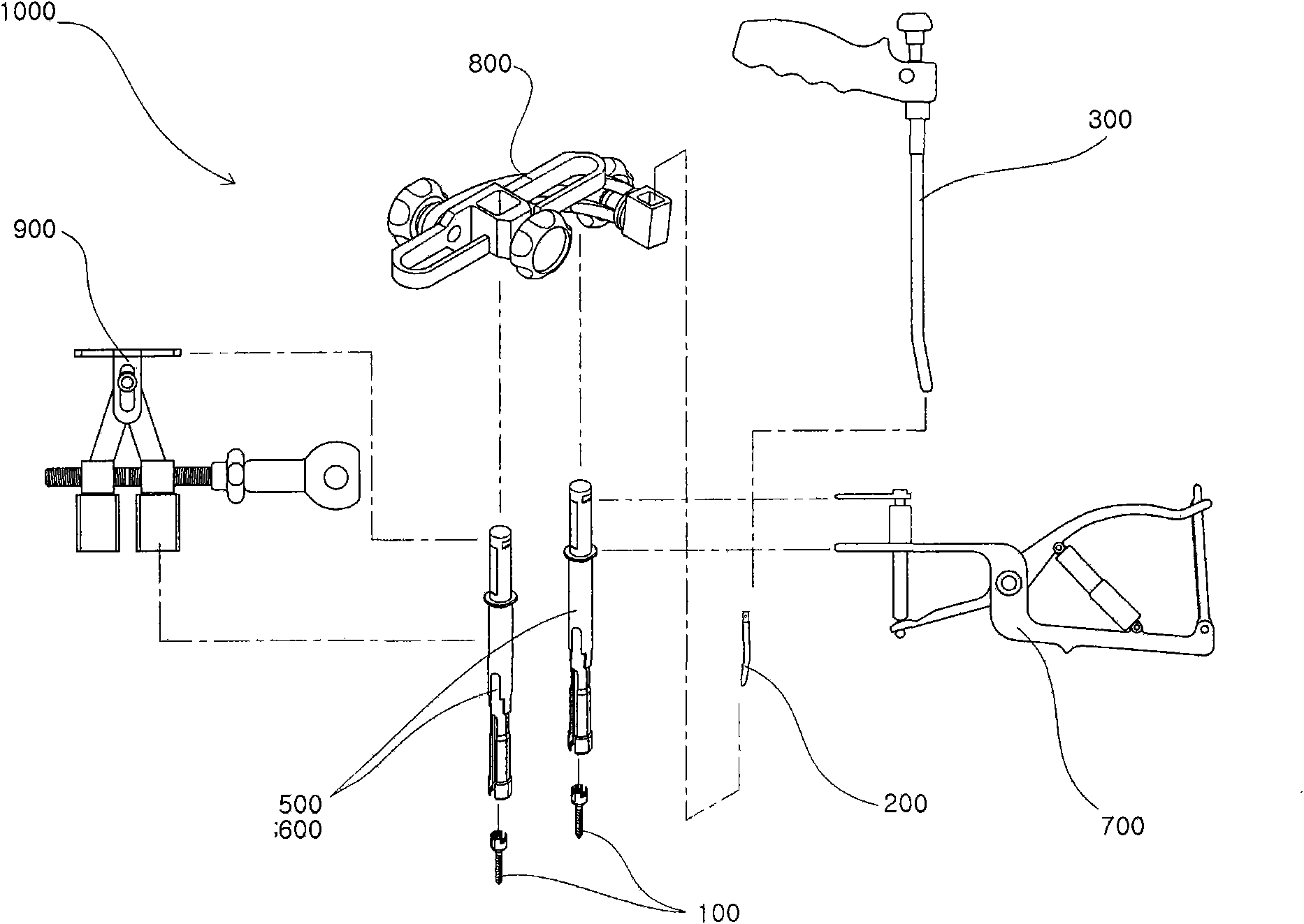
[0058] figure 2 It is a diagram showing the overall structure of the spinal minimally invasive surgery system 1000 of the present invention and the schematic configuration of the connection relationship between the vario...


PUM


Abstract

A rod holder configured to operate in a two-stage loading manner allows a rod to be easily received. A minimally invasive system for spinal surgical operation allows a rod to be more accurately and stably received to a pedicle screw inserted into a vertebra by using the rod holder, a rod guide and a rod guide holder. The rod holder may control a rod with three stages: a first loading stage for moving back and fixing a loading unit to fixedly grip the rod; a second loading stage for rotatably gripping the rod; and a rod mounting stage for separating the rod from the rod holder. The spine surgery system includes a pair of rod guides connected to upper ends of a pair of pedicle screws to form a moving path of the rod; a rod holder; and a rod guide holder for defining an insertion path.

Description

technical field [0001] The present invention relates to bar grippers, and more particularly to bar grippers configured to operate in a two-stage loading mode for easy loading of bars. [0002] In addition, the present invention relates to a minimally invasive surgery system for the spine, and more specifically, to a minimally invasive surgery system for the spine that can use the above-mentioned rod holder, rod Guides and rod guide clamping components for more accurate and stable installation of rods into pedicle screws inserted into the vertebrae with minimal damage to tissue or nerves at the surgical site. Background technique [0003] Generally speaking, the spine is usually composed of 24 vertebrae (excluding the sacrum), and the joints called intervertebral discs between the vertebrae support the spine and act as cushions. As a result, the spine not only helps maintain the posture of the human body, but also becomes the basis of movement and plays an important role in ...

Claims


Application Information

Patent Timeline
Patent Type & Authority Applications(China)
IPC IPC(8): A61B17/92A61B17/70A61B17/90
CPCA61B17/7074A61B17/708A61B17/7086A61B17/7089A61B17/7011A61B17/7085A61B17/701A61B17/70A61B17/88
Inventor 辛敏植金镇绚
Owner GS MEDICAL CO LTD
Why Eureka
Try Eureka