Heat backward extrusion molding process of large-sized cup-shaped piece

A technology of hot reverse extrusion and forming process, which is applied in the direction of metal extrusion dies, etc., and can solve the problems of reducing the forming force of hot reverse extrusion, reducing the forming force of generator retaining ring hot forging ring billet, and low production efficiency. , to achieve the effect of reducing the back-extrusion forming force, the labor-saving effect is obvious, and the production efficiency is improved

Active Publication Date: 2011-04-27
NANJING DEV ADVANCED MFG
View PDF7 Cites 16 Cited by
  • Summary
  • Abstract
  • Description
  • Claims
  • Application Information

AI Technical Summary

Problems solved by technology

[0004] In order to reduce the hot reverse extrusion forming force, the patent application "A Method and Die for Making Hot Forging Ring Blank of Generator Guard Ring (Application No. 200510012565.2)" adopts the method of wrapping the blank to reduce the size of the generator retainer ring. Forming force when hot forging ring blanks, the patent application "a large ring tube forging hot extrusion molding process and device (application number is 200910074230.1)" adopts the method of dividing one deformation into multiple deformations to reduce the size of large ring tubes These methods can reduce the hot reverse extrusion forming force and achieve the purpose of "small equipment doing big work", but the production efficiency is low

Method used


Image

  • Heat backward extrusion molding process of large-sized cup-shaped piece
  • Heat backward extrusion molding process of large-sized cup-shaped piece
  • Heat backward extrusion molding process of large-sized cup-shaped piece

Examples


Embodiment Construction

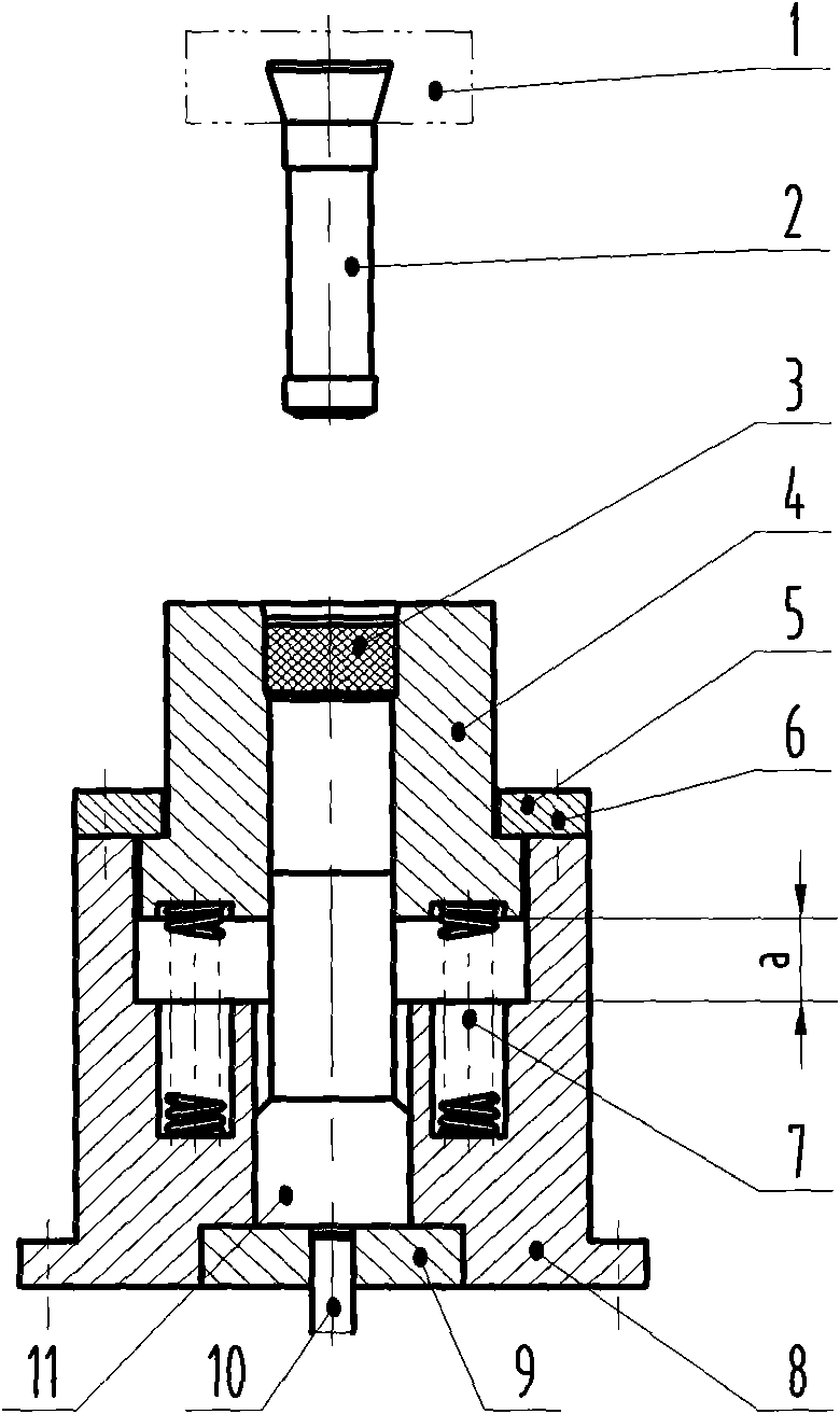
[0035] like Figure 1 to Figure 9 As shown, the specific steps of a hot reverse extrusion molding process of a large cup-shaped part are:

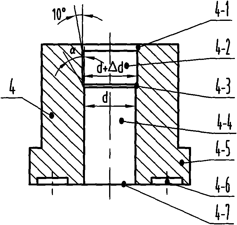
[0036] ① Place the heated billet 3 in the material chamber 4-2 of the reverse extrusion cylinder 4;

[0037] ②The pressure head 1 of the press presses down, driving the counter-extrusion punch 2 to touch the blank 3;

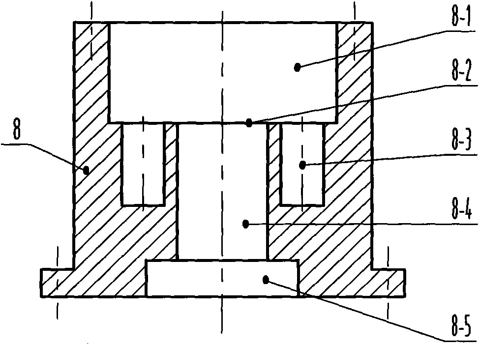
[0038] ③The press head 1 continues to press down, driving the counter-extrusion punch 2 to press down the billet 3, and the counter-extrusion cylinder 4 starts to slide downward along the wall surface of the inner cavity 8-1 at the upper end of the base 8 driven by the billet 3, And compress n evenly distributed cylindrical helical compression springs 7 until the lower bottom surface 4-7 of the anti-extrusion cylinder 4 is in contact with the bottom plane 8-2 of the upper end inner cavity 8-1 of the base 8, and n is a positive integer;

[0039] ④The pressure head 1 of the press continues to press down, driving the counter-...


PUM


Abstract

The invention discloses a heat backward extrusion molding process of a large-sized cup-shaped piece, relating to a backward extrusion molding method. By using the invention, the forming force for the heat backward extrusion of the large-sized cup-shaped piece can be reduced and the problem in the prior art that the production efficiency is low is solved. The heat backward extrusion molding process comprises the following concrete steps of: (1) placing a heat blank in a material accommodating cavity; (2) downwards pressing a pressure head to enable a backward extrusion punch head to be contacted with the blank; (3) downwards pressing the pressure head and allowing a backward extrusion cylinder to downwards slide along an inner cavity of a base and compress a spring until the spring contacts with the bottom plane of the inner cavity of the base; (4) downwards pressing the pressure head to enable all blanks to be reduced and extruded to a backward extrusion cavity to be attached to an ejector rod; (5) downwards pressing the pressure head and starting the backward extrusion molding process until the process is finished; (6) backward lifting the pressure head, lifting the backward extrusion cylinder, limiting a stamped part by a stripper plate to separate from the backward extrusion punch head, allowing the ejector rod to upwards eject and then taking out the stamped part after the stamped part is separated from the backward extrusion cylinder; (7) retracting the ejector rod and allowing an ejecting material to fall off and ensuring that a die restores the initial state; and (8) repeating the process steps from (1) to (7) and continuously finishing the heat backward extrusion molding of the large-sized cup-shaped piece.

Description

technical field [0001] The invention belongs to the technical field of cup-shaped parts forming, and in particular relates to a hot back-extrusion forming method for large cup-shaped parts. Background technique [0002] Reverse extrusion molding technology is an advanced metal pressure processing technology with less cutting and no cutting. It has the characteristics of "high efficiency, high quality and low consumption", and has high use value in technology and economy. [0003] Cup-shaped parts are typical parts of reverse extrusion. For the preparation of cup-shaped parts, the reverse extrusion molding technology is mostly used at home and abroad. Since the material is in a state of three-dimensional compressive stress during the reverse extrusion molding process, the material has strong resistance, and when the metal flows, it moves relative to the punch and die, and the friction is relatively large, which requires high equipment tonnage. In order to reduce the forming...

Claims


Application Information

Patent Timeline
Patent Type & Authority Applications(China)
IPC IPC(8): B21C23/20B21C25/02
Inventor 田继红张利
Owner NANJING DEV ADVANCED MFG
Why Eureka
Try Eureka