Buckle device for adjusting and clamping a strap

a strap and buckle technology, applied in the field of buckle devices for adjusting and clamping straps, can solve the problems of affecting the movement of the strap, affecting the adjustment of the strap, so as to reduce the friction and enhance the relative sliding movement of the two rings

Active Publication Date: 2016-09-06
ZEDEL CORP
View PDF8 Cites 8 Cited by
  • Summary
  • Abstract
  • Description
  • Claims
  • Application Information

AI Technical Summary

Benefits of technology

[0005]The object of the invention consists in providing a buckle device with double rings wherein the loosening handling operation when the strap is under tension is made easier, without increasing the overall dimensions of the buckle.
[0006]The attachment device according to the invention is characterized in that the buckle is associated with a positioning shim housed opposite the slot, surrounding a first closed turn of the strap, said positioning shim separating the top strand and the bottom strand of said turn from one another to reduce the friction effect when relative movement takes place between the two rings.
[0008]The presence of the shim according to the invention enables friction to be reduced and the relative sliding movement of the two rings to be enhanced, both when the strap is tightened and loosened. The buckle is free to withdraw when loosening is performed, and free to rotate for complete opening, for example to remove the belt of a harness

Problems solved by technology

In this type of known attachment buckles, it is difficult to perform certain movements necessary for when the resistant strap is under tension.
The tension of the strap causes reactions on the top crosspiece and hampers movement of the latter in translation and rotation of the buckle.
The two rings are in fact pressed against one another, and the resulting friction effect hampers their relative movement, and pinching of the strap in the slot on the adjustment side is imperfect under certain conditions.

Method used


Image

  • Buckle device for adjusting and clamping a strap
  • Buckle device for adjusting and clamping a strap
  • Buckle device for adjusting and clamping a strap

Examples


Embodiment Construction

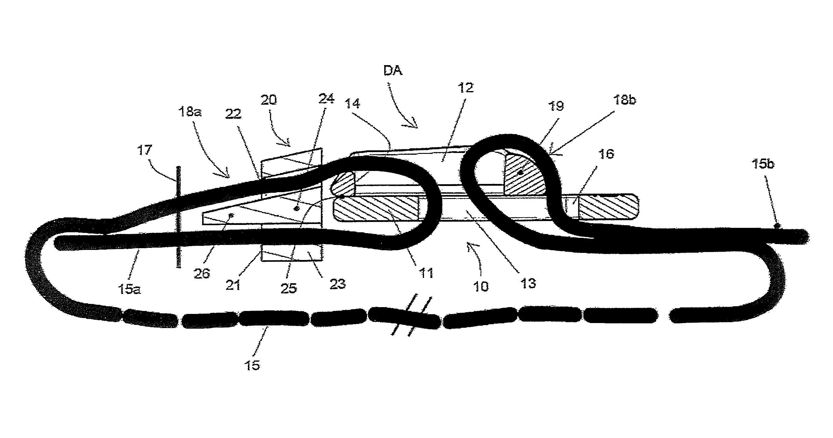
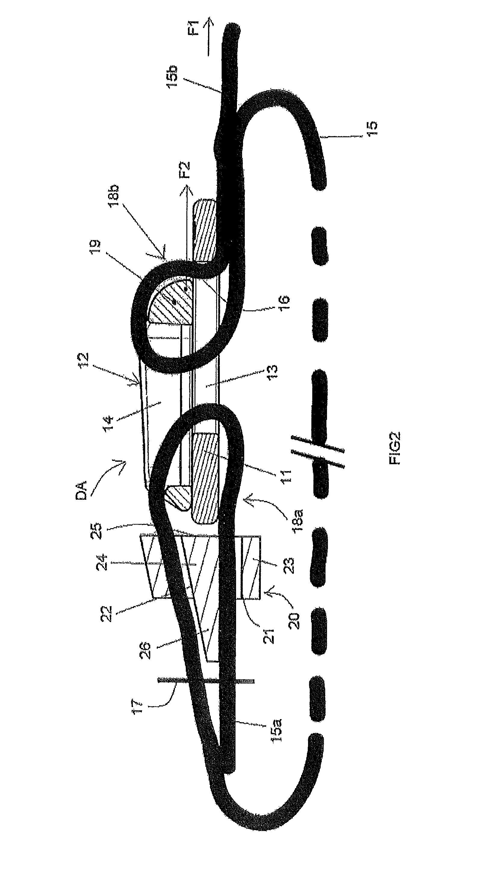
[0013]In FIGS. 1 to 3, attachment device DA comprises a buckle 10 composed of a pair of superposed rings 11, 12 having rectangular or trapezoid structures of different dimensions. The larger first ring 11 comprises a first opening 13 located underneath a rectangular second opening 14 arranged in second ring 12 which is of smaller size. The width of strap 15 is slightly smaller than that of openings 13, 14 to prevent any friction of strap 15 against the opposite lateral edges of rings 11, 12.

[0014]The strap 15 passes through the two openings 13, 14 in the following manner:

[0015]End 15a (on the left) of strap 15 passes through the two openings 13, 14, forming a first turn 18a closed by a seam 17 over the whole width of the strap. Buckle 10 is thus permanently attached to strap 15 by this stitched first turn 18a.

[0016]End 15b (on the right) of strap 15 is then inserted in a transverse slot 16 situated between the outer edge of second ring 12 and the adjacent side of first opening 13. ...


PUM


Abstract

An attachment device for tightening an adjustable resistant strap, comprising a buckle composed of a pair of superposed rings of different dimensions. The buckle is associated with a positioning shim housed around a closed first turn arranged opposite the blocking slot of the strap. The positioning shim is configured to separate the top strand and the bottom strand of said turn from one another. This results in a reduction of the friction effect when relative movement takes place between the two rings. The shim is equipped for this purpose with two guide apertures through which the bottom strand and the top strand of the closed turn attached to the buckle respectively pass.

Description

BACKGROUND OF THE INVENTION[0001]The invention relates to a buckle device for adjusting and clamping a strap, said buckle being composed of a pair of superposed rings presenting rectangular frames of different dimensions, the larger first ring comprising a first rectangular opening located under a second rectangular opening arranged in the second ring of smaller size so as to define a transverse slot for passage of the strap, the slot being arranged between one of the outer edges of the second ring, and the adjacent side of the first opening of the first ring, the buckle being located either in a blocking position of the strap in the slot following tensioning, or in a releasing position after a relative movement between the two rings resulting in an increase of the passage area in the slot.[0002]Such a buckle is in particular used for securing a safety sit harness strap.STATE OF THE ART[0003]According to the buckle described in the document EP 614626, the second ring is fitted float...

Claims


Application Information

Patent Timeline
Patent Type & Authority Patents(United States)
IPC IPC(8): A44B11/18A44B11/12
CPCA44B11/18A44B11/125Y10T24/2153
Inventor HEDE, JEAN-MARCBOUQUIER, BENO T
Owner ZEDEL CORP
Why Eureka
Try Eureka