Lens shift measuring apparatus, lens shift measuring method, and optical module manufacturing method

A technology for measuring equipment and offset, applied in the direction of testing optical performance, optics, measuring devices, etc., can solve problems such as optical axis or optical module optical coupling efficiency reduction

Inactive Publication Date: 2011-04-27
RENESAS ELECTRONICS CORP
View PDF2 Cites 16 Cited by
  • Summary
  • Abstract
  • Description
  • Claims
  • Application Information

AI Technical Summary

Problems solved by technology

[0005] In this way, if the position of the focus point of the laser diode is shifted from the center of the CAN package, it will take time to adjust the light in the following process when the CAN package is combined with an optical fiber or a socket to constitute an optical module (optical semiconductor device). Reduced optical coupling efficiency of axes or optical modules

Method used


Image

  • Lens shift measuring apparatus, lens shift measuring method, and optical module manufacturing method
  • Lens shift measuring apparatus, lens shift measuring method, and optical module manufacturing method
  • Lens shift measuring apparatus, lens shift measuring method, and optical module manufacturing method

Examples


no. 1 example

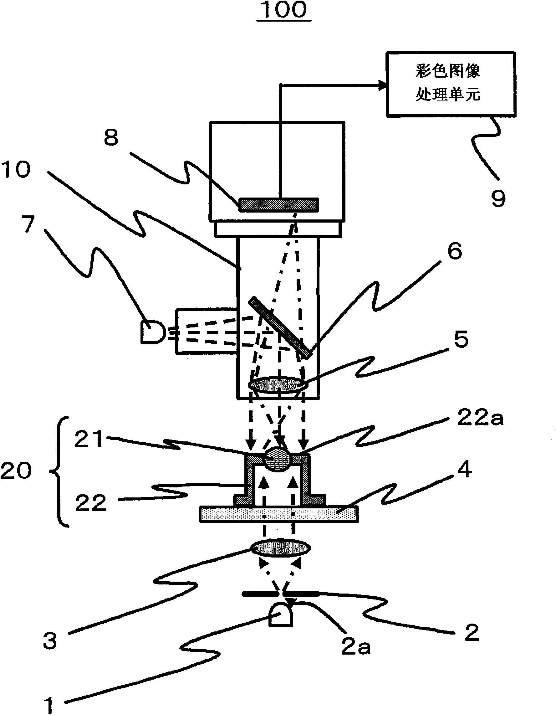
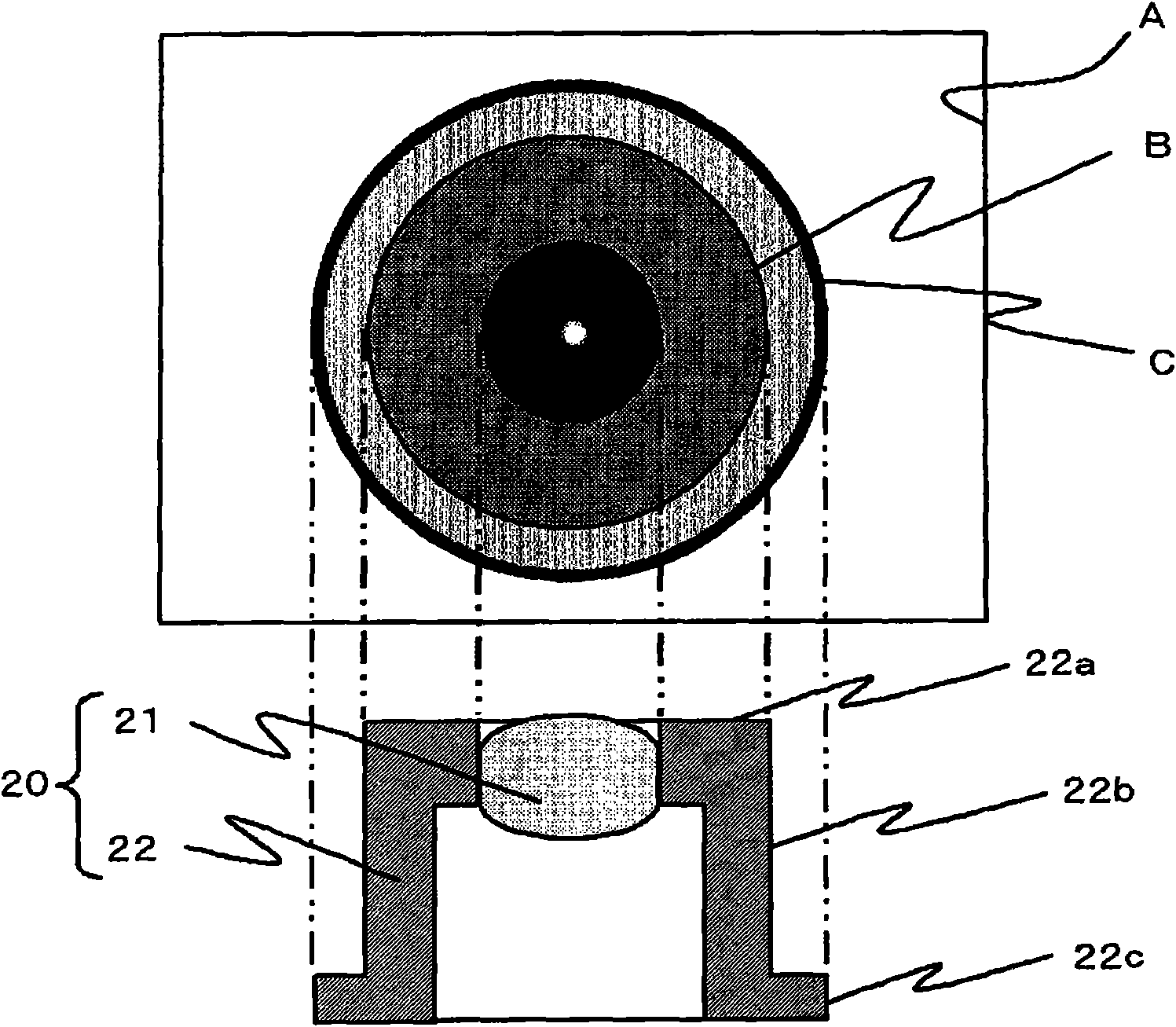
[0038] figure 1 is a schematic front cross-sectional view of the lens shift measuring apparatus 100 according to the first embodiment. Figure 5 is a flowchart showing the operation flow of the lens shift measuring method according to the first embodiment. Figure 9 is a schematic cross-sectional view showing an example of the optical module 150 manufactured by the optical module manufacturing method according to the first embodiment.

[0039] The lens shift measuring apparatus 100 according to this embodiment includes a radiation unit (for example, configured to irradiate epi-illumination light using epi-illumination light source 7 and to irradiate transmitted illumination light using trans-illumination light source 1 ), which radiates light to an attached On the lens member (for example, lens cover 20), the lens-attached member has a lens 21 and a frame (for example, cover 22) to hold the lens 21, thereby generating reflected light from the frame and passing through it by f...

no. 2 example

[0129] Figure 10 is a schematic front cross-sectional view of the lens shift measuring apparatus 200 according to the second embodiment. Figure 11 is a flowchart showing the flow of operations of the lens shift measuring method according to this second embodiment.

[0130] In the first embodiment, description has been made on an example of the case where the wavelengths of the epi-illumination light and the transmission illumination light are set to be different from each other, and an image of the color of the epi-illumination light is extracted from a color image obtained by one imaging and images of the color of the transmitted illumination light, and perform image processing separately. Meanwhile, in the second embodiment, an example of a case where imaging based on epi-illumination light and imaging based on transmitted illumination light are performed at different timings will be described.

[0131] In the case of this embodiment, the wavelengths of the epi-illuminat...


PUM


Abstract

The lens shift measuring apparatus calculates a position of a predetermined portion of a frame body, on the basis of an imaging result obtained by imaging reflected light from the frame body, in a state in which light is irradiated onto a lens-attached member having a lens and the frame body to hold the lens, such that the reflected light from the frame body is generated, and calculates a position of a focusing spot, on the basis of an imaging result obtained by imaging light transmitted through the lens, in a state in which the light is irradiated onto the lens-attached member, such that the focusing spot formed by focusing the light transmitted through the lens by the lens is generated, and calculates a shift amount of the position of the focusing spot with respect to the predetermined portion as the shift of the lens.

Description

[0001] This application is based on Japanese Patent Application No. 2009-224989, the contents of which are incorporated herein by reference. technical field [0002] The invention relates to a lens offset measurement device, a lens offset measurement method and an optical module manufacturing method. Background technique [0003] For example, in CAN packaging of optical semiconductor elements for optical communication, packaging is generally performed using a cover (hereinafter, referred to as a lens cover) in which a lens is hermetically sealed to a central portion in order to achieve optical coupling with an optical fiber or with a user. Optical coupling to a socket for connecting an optical fiber. The lens cover is hermetically sealed by resistance welding with respect to a disc-shaped block (stem: stem) at which a chip such as a laser diode is mounted. [0004] When the lens cover is hermetically sealed, the stem and the lens cover are positioned based on their external...

Claims


Application Information

Patent Timeline
Patent Type & Authority Applications(China)
IPC IPC(8): G01M11/00G01B11/00G02B6/42
CPCG02B6/4222G01M11/0221G02B6/4221G02B6/4227G02B6/4204
Inventor 田中良治
Owner RENESAS ELECTRONICS CORP
Why Eureka
Try Eureka