Supercharge Your Innovation With Domain-Expert AI Agents!

Monitoring and control system and monitoring and control device

A technology for controlling equipment and control systems, applied in the direction of comprehensive factory control, electrical program control, instruments, etc., can solve problems such as unintentionally displaying office buildings, intruding into office buildings, and feeling inconvenient

Inactive Publication Date: 2011-04-27
PANASONIC CORP
View PDF6 Cites 4 Cited by
  • Summary
  • Abstract
  • Description
  • Claims
  • Application Information

AI Technical Summary

Problems solved by technology

For example, some users turn on the same lighting equipment whenever they enter the room of the office building, and may feel inconvenient when operating the operation terminal in the same way every time
Furthermore, if operation buttons are configured and displayed without change for all users as in the conventional method, it may be inconvenient for one user to omit or display an operation button that is frequently used at a position where it is difficult for the user to manipulate the operation button.
[0008] In addition, although the load placed remotely can be conveniently controlled by using conventional remote monitoring and control equipment, it may cause leakage of information to display the operation button for controlling the load by the multi-function switch
For example, when traditional remote monitoring and control equipment controls switching on and off loads such as lighting equipment in an office building, the configuration of the office building, detailed lighting information, etc. may be displayed unintentionally, and the information of the office building may be Illegally misused by intruders to break into office buildings
[0009] Also, if the multifunction switch is open to the public and not restricted to authorized employees, the load may be used unnecessarily, resulting in wasted energy

Method used


Image

  • Monitoring and control system and monitoring and control device
  • Monitoring and control system and monitoring and control device
  • Monitoring and control system and monitoring and control device

Examples


no. 1 example

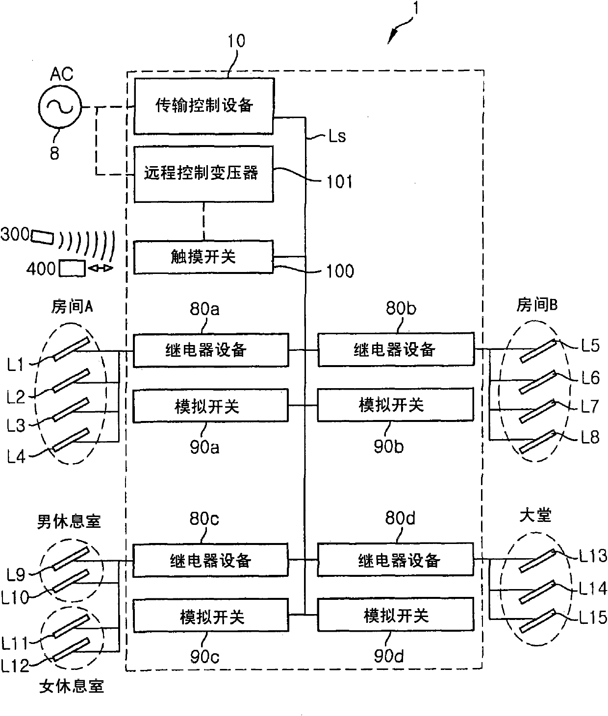
[0076] First, a first embodiment of the present invention will be described. Such as figure 1 As shown in , the remote monitoring and control system 1 includes a transmission control device 10, four relay devices 80a to 80d, four analog switches 90a to 90d, and a touch switch 100 used as a monitoring and control device.

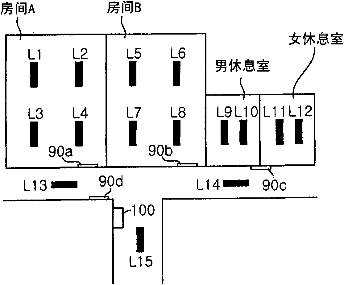
[0077] figure 2 is the floor plan of one floor of the office building occupied by Company P. The remote monitoring and control system 1 of this embodiment is applied to this floor in an office building. Such as figure 2 As shown in , the loads L1 to L4 are installed on the ceiling portion of the room A, and the analog switch 90a for controlling the loads L1 to L4 is provided on the wall surface of the room A near the entrance of the room A.

[0078] Similarly, loads L5 to L8 are installed on the ceiling portion of room B, and an analog switch 90b for controlling loads L5 to L8 is provided on the wall surface of room B near the entrance of room B. The m...

no. 2 example

[0156] Next, a second embodiment of the present invention will be described with reference to the relevant drawings.

[0157] The configuration of the remote monitoring and control system 11 of the second embodiment is similar to that of the remote monitoring and control system 1 of the first embodiment except for the touch switch 100'. Accordingly, components having substantially the same configuration and function are denoted with similar reference numerals, and thus, redundant descriptions thereof are omitted herein.

[0158] Such as Figure 20 As shown in , according to the present embodiment, loads L19 and L20 and loads L21 and L22 are installed in the machine room and the accounting department, respectively.

[0159] In this embodiment, once the user ID is read out from the user's identification 300, the touch switch 100' determines whether the user ID has display authorization, and if the user ID has display authorization, the touch switch 100' displays operation scre...


PUM


Abstract

A remote monitoring and control system includes a monitoring and control device operated to control loads; and a load control device for controlling the loads based on the operation of the monitoring and control device. The monitoring and control device includes: a display unit for displaying an operation screen including operation keys for controlling corresponding loads; an input receiving unit for receiving an input through the displayed operation keys; a reading unit for reading out a user ID; a storage unit for storing load-identifying information identifying loads and control information having control contents of the loads; and a determining unit for searching the storage unit if a user ID is read out, and determining the load-identifying information and the control information which correspond to the user ID, and the load control device controls the loads identified based on the load-identifying information, depending on the control contents of the control information.

Description

technical field [0001] The present invention relates to a remote monitoring and control system for monitoring and controlling loads such as lighting equipment, and monitoring and control equipment used in the remote monitoring and control system. Background technique [0002] A conventional remote monitoring and control system includes, for example, an operation terminal with a plurality of operation buttons for controlling a load, and the operation terminal is used as a monitoring and control device; a control terminal of the relay circuit; and a transmission control device respectively connected to the operation terminal and the control terminal through signal lines (for example, see Japanese Patent Application Publication No. H10-243478 (JP10-243478A1)). [0003] In this system, addresses are individually assigned to the load and the operation buttons of the operation terminal. [0004] Once the operation terminal receives an input of a specific operation button, a signa...

Claims


Application Information

Patent Timeline
Patent Type & Authority Applications(China)
IPC IPC(8): G05B19/418G06F3/048
CPCH05B37/0272H05B47/19H05B47/195
Inventor 锅岛秀生中西真理
Owner PANASONIC CORP
Features
  • R&D
  • Intellectual Property
  • Life Sciences
  • Materials
  • Tech Scout
  • Unparalleled Data Quality
  • Higher Quality Content
  • 60% Fewer Hallucinations
Learn More