Contact type image sensor

An image sensor and contact technology, applied in image communication, instruments, electrical components, etc., can solve the problems of large number of ultraviolet LEDs, unacceptable batch production, poor uniformity, etc., achieve low cost, solve serious attenuation phenomenon, and ensure uniformity The effect of sex and intensity

Active Publication Date: 2011-04-27
WEIHAI HUALING OPTO ELECTRONICS CO LTD
View PDF7 Cites 1 Cited by
  • Summary
  • Abstract
  • Description
  • Claims
  • Application Information

AI Technical Summary

Problems solved by technology

[0002] We know that the existing contact image sensor with ultraviolet information identification function used for anti-counterfeiting banknotes in the banking system has a circuit board under the frame, a photoelectric conversion chip is provided on the circuit board, and a lens is installed above the photoelectric conversion chip. The side of the lens is provided with a linear light source, and the linear light source can be provided on one side of the lens, or on both sides of the lens. Among the linear light sources installed on the side, there is a linear light source that emits ultraviolet light. Since ultraviolet light will be severely attenuated when transmitted in an ordinary light guide, and the wavelength of ultraviolet light will change when it encounters ordinary reflection patterns, the ultraviolet light linear light source usually uses ultraviolet light. The structure in the form of an LED array avoids the problem of attenuation of ultraviolet light transmission and wavelength change after ultraviolet light reflection caused by the use of light guides and reflective patterns. The disadvantage of the array form of ultraviolet linear light source is that the number of ultraviolet LEDs used is large and the cost is high. , poor uniformity, and high power consumption. The price of contact image sensors made of array-form ultraviolet light sources is difficult for users to mass-produce. The cost of array-form ultraviolet light sources accounts for 5% of the cost of contact image sensors. More than ten, and the uniformity of the light source is guaranteed by the arrangement density of LEDs. The higher the LED density, the higher the cost

Method used


Image

  • Contact type image sensor
  • Contact type image sensor
  • Contact type image sensor

Examples


Embodiment Construction

[0016] The present invention will be further described below in conjunction with drawings and embodiments.

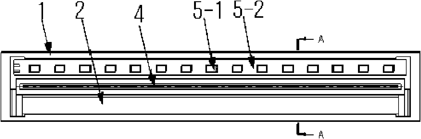
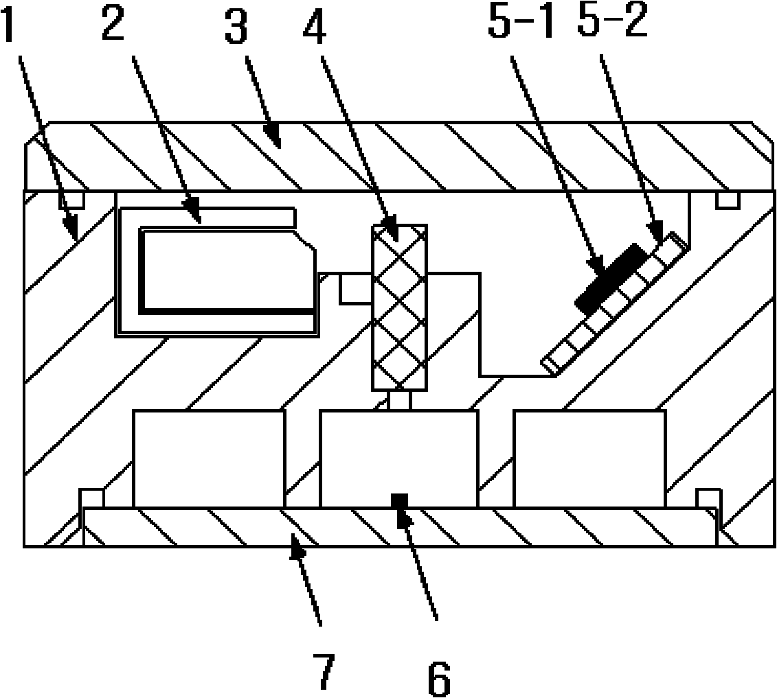
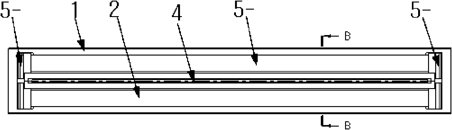
[0017] Such as image 3 , Figure 4 As shown, a contact image sensor is provided with a frame 1, a circuit board 7 is provided under the frame 1, a photoelectric conversion chip 6 is provided on the circuit board 7, a lens 4 is installed above the photoelectric conversion chip 6, and a lens 4 is provided on the side of the lens 4. Light source 2, the top of frame 1 is provided with glass plate 3, above-mentioned is the same as prior art, belongs to those skilled in the art should know, this does not go into details, the feature of the present invention is that lens 4 side is provided with by ultraviolet LED5-1, LED circuit An ultraviolet light source composed of plate 5-2, light guide body 5-3 and metal light guide plate 5-4, ultraviolet LED5-1 is located at the end of light guide body 5-3, light guide body 5-3 of the present invention can be one end Ultraviolet LEDs ...


PUM


Abstract

The invention relates to an image reading device, in particular to a contact type image sensor in which an ultraviolet linear light source is in a light conductor type. The contact type image sensor comprises a frame, wherein a circuit board is arranged below the frame, and a photoelectric conversion chip is arranged on the circuit board; a lens is arranged above the photoelectric conversion chip, and the light source is arranged at the side face of the lens; and a glass plate is arranged above the frame. The contact type image sensor is characterized in that the linear light source consisting of an ultraviolet light-emitting diode (LED), a light conductor and an LED circuit board is arranged at the side face of the lens, and the ultraviolet LED is arranged at the end of the light conductor. The contact type image sensor provided by the invention has the advantages of low cost, low power consumption, high uniformity, high sensitivity of ultraviolet information identification and the like.

Description

Technical field [0001] The invention relates to an image reading device, in particular to a contact image sensor in which the ultraviolet linear light source is a light guide. Background technique [0002] We know that the existing contact image sensor with ultraviolet information identification function used for anti-counterfeiting banknotes in the banking system is provided with a circuit board under the frame, a photoelectric conversion chip is provided on the circuit board, and a lens is installed above the photoelectric conversion chip. The side of the lens is provided with a linear light source, and the linear light source can be arranged on one side of the lens, or on both sides of the lens. Among the linear light sources installed on the side, there is a linear light source that emits ultraviolet light. Since ultraviolet light will be severely attenuated when transmitted in an ordinary light guide body, and the wavelength of ultraviolet light will change when it enco...

Claims


Application Information

Patent Timeline
IPC IPC(8): G07D7/12
CPCH04N2201/03112H04N2201/03129H04N1/0313G07D7/121H04N1/1017
Inventor 泽江哲则刘振翔
Owner WEIHAI HUALING OPTO ELECTRONICS CO LTD
Why Eureka
Try Eureka