Supercharge Your Innovation With Domain-Expert AI Agents!

Plasma display apparatus and driving methoid for plasma display apparatus

A technology for display panels and display devices, which is applied to alternating current plasma display panels, static indicators, tube structural parts, etc., and can solve problems such as electrode resistance reduction, scan electrode peak current rise, and pulse rise, etc.

Inactive Publication Date: 2011-04-27
PANASONIC CORP
View PDF10 Cites 2 Cited by
  • Summary
  • Abstract
  • Description
  • Claims
  • Application Information

AI Technical Summary

Problems solved by technology

[0007] However, in the case of using a material for reducing the loss in the electrode resistance, or using a plurality of display electrode pairs, the resistance value of the electrode decreases, and the peak current of the scanning electrode increases.
As a result, it may be necessary to use a sustain driving circuit component with a large rated current, or if such a component cannot be selected, there is a problem that it is necessary to increase the resistance value of the display electrode pair or gradually increase the pulse.

Method used


Image

  • Plasma display apparatus and driving methoid for plasma display apparatus
  • Plasma display apparatus and driving methoid for plasma display apparatus
  • Plasma display apparatus and driving methoid for plasma display apparatus

Examples


Embodiment approach

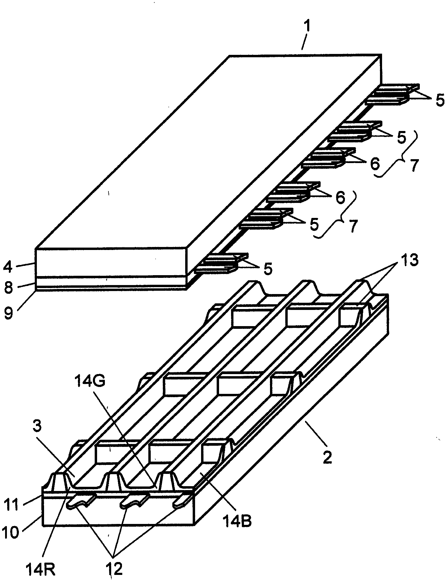
[0064] Below, use Figure 1 to Figure 18 , the plasma display device and the driving method of the panel according to the embodiment of the present invention will be described, but the embodiment of the present invention is not limited thereto. First, use Figure 1 ~ Figure 3 The overall configuration of the panel according to the embodiment of the present invention will be described.

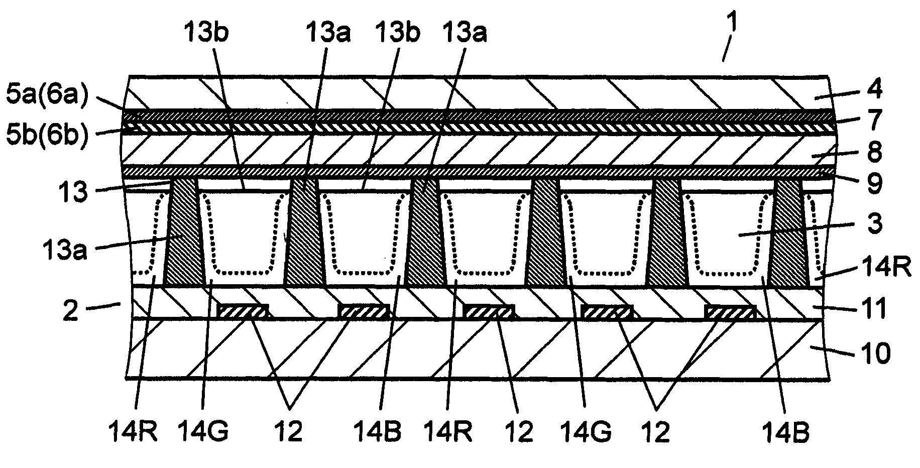
[0065] figure 1 It is an exploded perspective view showing the state where the front panel 1 and the back panel 2 are separated in the panel according to the embodiment of the present invention. figure 2 It is a cross-sectional view when the front panel 1 and the back panel 2 are bonded to form a panel. like figure 1 , figure 2 As shown in the panels, the front panel 1 and the rear panel 2 are arranged to face each other so that the discharge space 3 is formed between the glass front panel 1 and the rear panel 2 .

[0066] In front panel 1 , scan electrodes 5 which are conductive first ...


PUM


Abstract

A plasma display apparatus has a sustain pulse generation circuit for generating a sustain pulse during a sustain period. The sustain pulse generation circuit generates at least two different sustain pulses whose rising parts have different gradients over the sustain period. Also, after the occurrence of the first two pulses in the sustain period and within the sustain period excluding an erasing pulse, the sustain pulse generation circuit generates a predetermined number of sustain pulses whose rising gradients become more steep toward the latter pulses at least at one of electrodes, continuously as sustain pulses whose gradients at the rising parts vary depending on the illumination rate of the plasma display in the sustain period.

Description

technical field [0001] The invention relates to a plasma display device and a driving method for a wall-mounted television and a large monitor and a plasma display panel. Background technique [0002] In an AC surface discharge type panel typical of a plasma display panel (hereinafter simply referred to as a "panel"), a plurality of discharge cells are formed between a front panel and a rear panel that are arranged to face each other. In the front panel, a plurality of display electrode pairs consisting of a pair of scan electrodes and sustain electrodes are formed parallel to each other on a front glass substrate, and a dielectric layer and a protective film are formed to cover these display electrode pairs. In the rear plate, a plurality of parallel data electrodes, a dielectric layer covering the data electrodes, and a plurality of barrier ribs parallel to the data electrodes are formed on the rear glass substrate. In addition, a phosphor layer is formed on the surface o...

Claims


Application Information

Patent Timeline
Patent Type & Authority Applications(China)
IPC IPC(8): G09G3/28G09G3/20G09G3/288G09G3/291G09G3/294G09G3/296G09G3/298
CPCG09G2310/066G09G2320/0228H01J11/24G09G3/2965G09G3/2022G09G3/2927G09G3/2946H01J11/12G09G2360/16H01J2211/38G09G2330/025H01J2211/245H01J2211/363
Inventor 辻田芳树武田实古泽诚司佐佐木健次
Owner PANASONIC CORP
Features
  • R&D
  • Intellectual Property
  • Life Sciences
  • Materials
  • Tech Scout
  • Unparalleled Data Quality
  • Higher Quality Content
  • 60% Fewer Hallucinations
Learn More