
Fastener punching machine

A technology for fasteners and driving machines, which is applied in the directions of staple staple tools, nailing tools, manufacturing tools, etc. The effect of moving in the reverse direction and reducing the cost of parts

Active Publication Date: 2011-05-04
MAX CO LTD
View PDF10 Cites 12 Cited by
  • Summary
  • Abstract
  • Description
  • Claims
  • Application Information

AI Technical Summary

Problems solved by technology

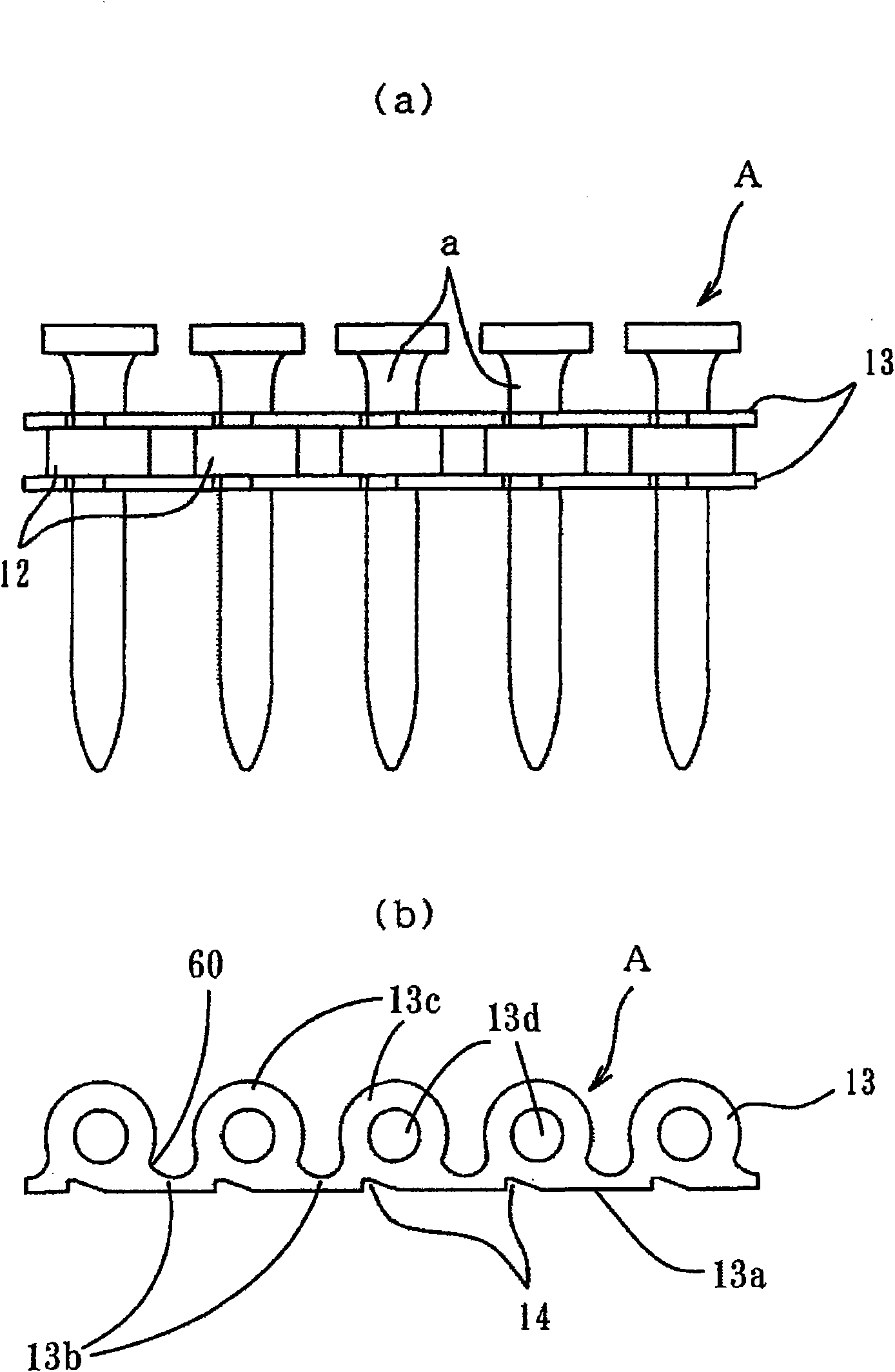
[0019] Like this, in all cases, even if the shape of the conventional connecting belt is intended to be used for conveyance or non-return, but the above-mentioned recessed portion of the conventional connecting belt is not used for engagement originally, so the connection cannot be made. Feed or check stabilization of fasteners

Method used


Image

  • Fastener punching machine
  • Fastener punching machine
  • Fastener punching machine

Examples


Embodiment Construction

[0077] (Nailer)

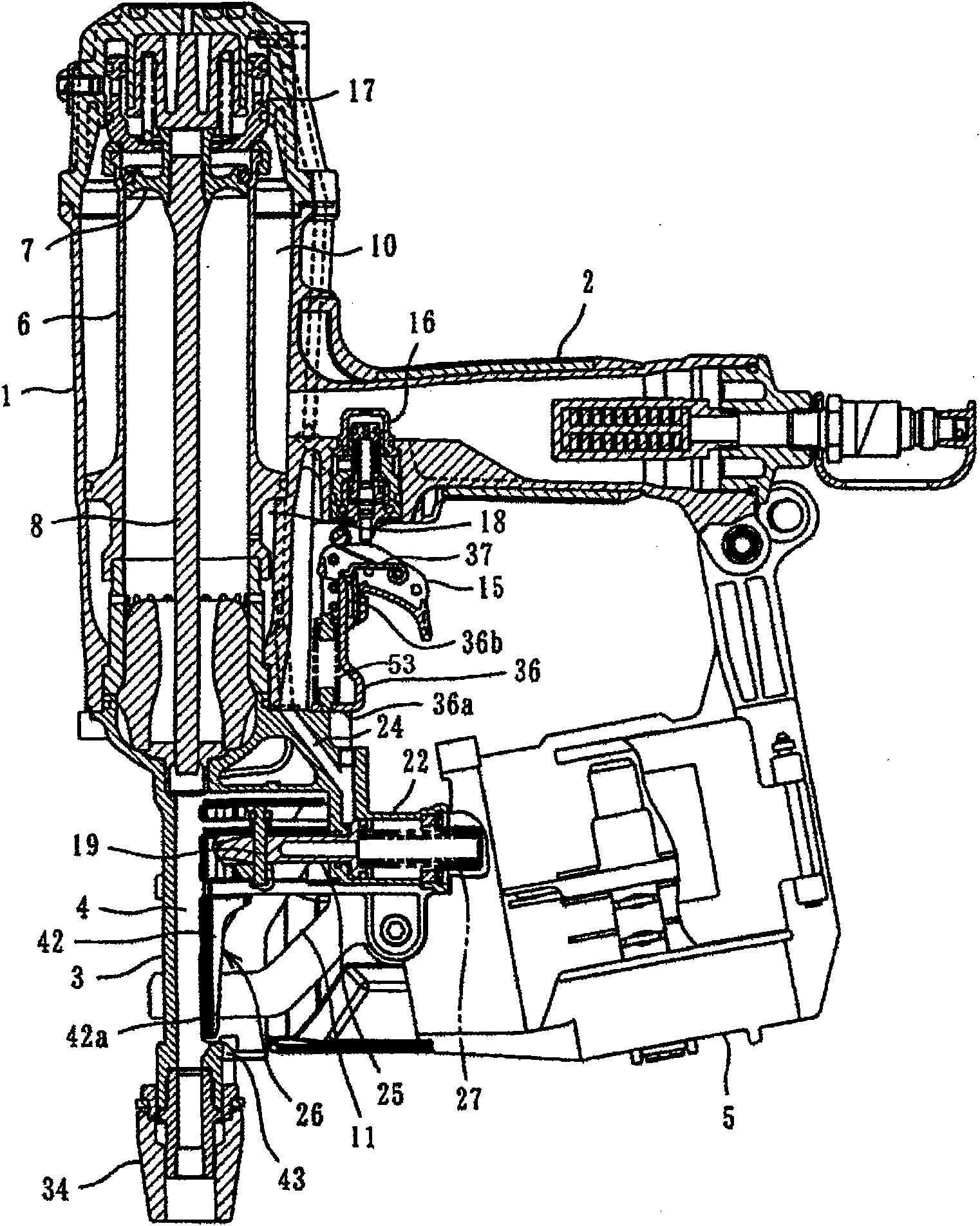
[0078] figure 1 A nailing machine as one embodiment of the fastener driving machine of the present invention is shown. The nailing machine is integrally provided with a handle 2 at the rear of the nailing machine main body 1, and a machine head 3 with an injection port 4 is integrally provided at the lower part of the nailing machine main body 1, and is connected to the rear of the machine head 3. A magazine 5 of nails is supplied to the injection port 4 , and a striking mechanism is provided in the nailer main body 1 . That is, the striking piston 7 is housed in the striking cylinder 6 and allowed to slide freely. A driving tool 8 is integrally fixed to the lower portion of the striking piston 7 , and the driving tool 8 is configured to slide in the injection port 4 of the hand piece 3 . In addition, an air chamber 10 for storing compressed air supplied from a compressed air supply source (not shown) such as an air compressor or the like is formed in the...


PUM


Abstract

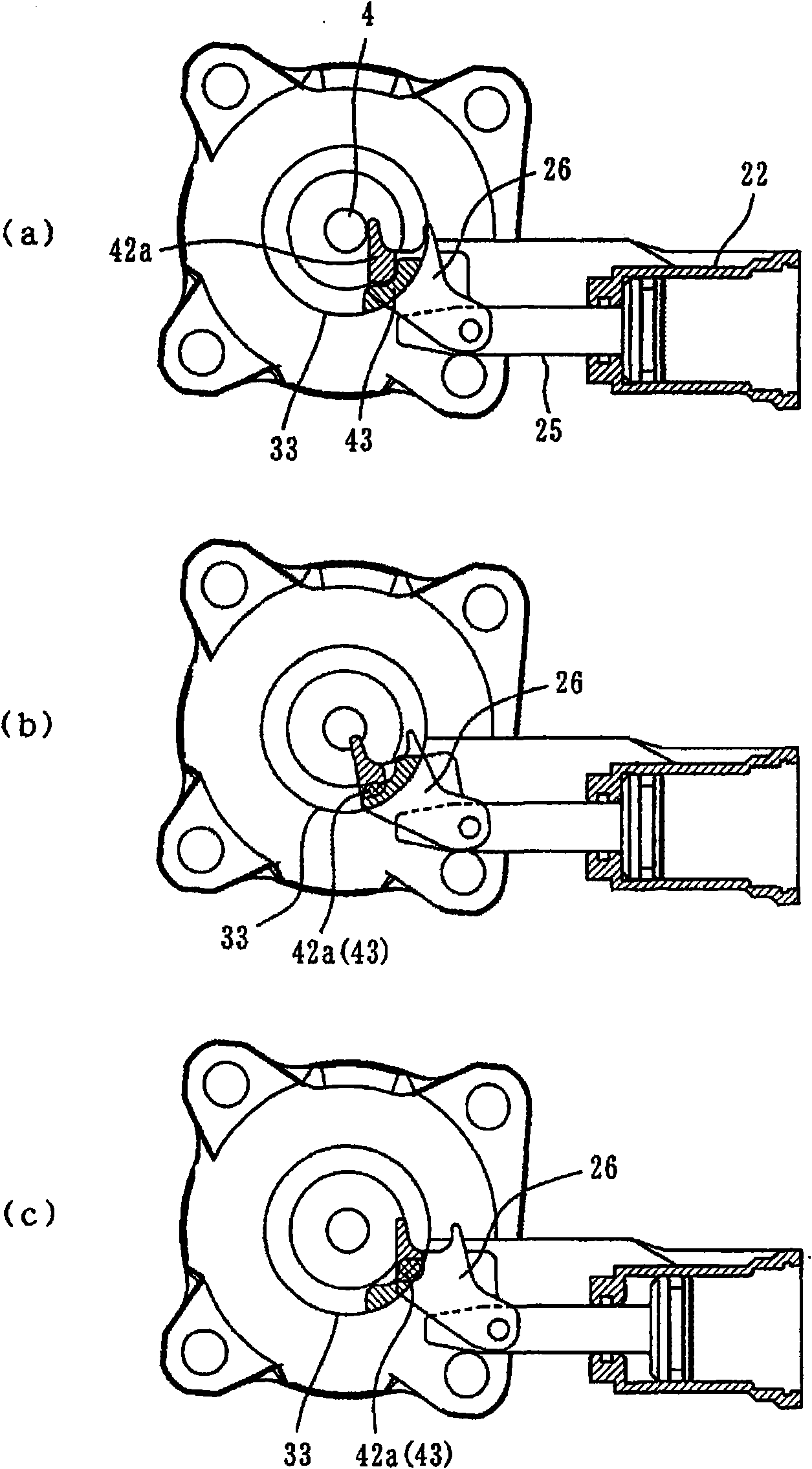
A fastener punching machine is provided with the following components: a conveying passage which is provided with an opening at a machine head (3) for punching; a conveying pawl (26) which is jointed with a connecting fastener (A) and moves in a conveying direction for transporting the connecting fastener (A) to a shooting outlet (4); a touch unit (33) which is freely equipped slidably along the machine head (3) and is pressed to the punched material for moving relatively to a punching machine body (1) and validating a starting operation of punching the fastener; and jointing parts (43,52) which are set on the touch unit (33) and can be jointed with the conveying pawl (26). The conveying pawl (2) can retreat and rotate from the conveying passage (11). The conveying pawl (26) can load the connecting fastener (A) to the conveying passage (11) without causing the rotation of the conveying pawl (26). The touch unit (33) is pressed to the punched material at a state that the conveying pawl (26) retreats and rotates, and the jointing parts (43,52) of the touch unit (33) are jointed with the conveying pawl (26).

Description

technical field [0001] The invention relates to a fastener driving machine, which has: a fastener conveying mechanism, which sends out the connecting fastener contained in the magazine from the conveying path of the fastener to the machine head with an injection port; And a contact arm, which is set to slide freely along the head and press against the material to be driven, so as to move relative to the head to make the driving start operation of the fastener effective. [0002] Furthermore, the present invention relates to a fastener driving machine, which uses air pressure, fuel gas, etc. Reliably prevent fasteners from moving in the direction opposite to the conveying direction when ejected. Background technique [0003] For example, in a nailing machine using compressed air as the driving source, the striking piston is driven by the high-pressure air supplied to the striking cylinder, and the striking unit is driven from the magazine to the nailing machine body by a str...

Claims


Application Information

Patent Timeline
Patent Type & Authority Applications(China)
IPC IPC(8): B25C1/00B25C7/00
Inventor 星野享道山本博纪武内贞良
Owner MAX CO LTD
Learn More