Check patentability & draft patents in minutes with Patsnap Eureka AI!

Structure and method for connecting underframe equipment bay and vehicle body

A technology for connecting structures and equipment cabins, which is applied in the direction of railway car body, railway car body parts, transportation and packaging, etc., which can solve the problem of high technical difficulty and component cost in the installation and positioning of equipment under the car, which affects the light weight of the car body chassis Quantitative design, unfavorable rail vehicle running speed and other issues, to achieve the effect of reducing design difficulty, reducing the weight of the car body, and improving aerodynamic performance

Inactive Publication Date: 2011-05-04
BOMBARDIER SIFANG QINGDAO TRANSPORTATION
View PDF0 Cites 3 Cited by
  • Summary
  • Abstract
  • Description
  • Claims
  • Application Information

AI Technical Summary

Problems solved by technology

[0003] The existing bracket-type suspension positioning system and method require a certain space to be reserved for the bracket, and because the equipment compartment for accommodating the equipment under the vehicle weighs about 10 tons, the bracket structure itself requires strict rigidity and strength design Requirements, for the installation and positioning of equipment under the vehicle, it poses high technical difficulty and component cost
[0004] In addition, the installation and positioning structure of the existing under-car equipment increases the volume and weight of the underframe, which is not conducive to improving the air resistance when the rail vehicle is running, and also affects the lightweight design of the underframe of the car body, which is not conducive to improving the operation of the rail vehicle. speed

Method used


Image

  • Structure and method for connecting underframe equipment bay and vehicle body
  • Structure and method for connecting underframe equipment bay and vehicle body
  • Structure and method for connecting underframe equipment bay and vehicle body

Examples


Embodiment 1

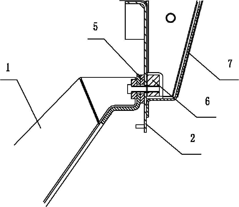
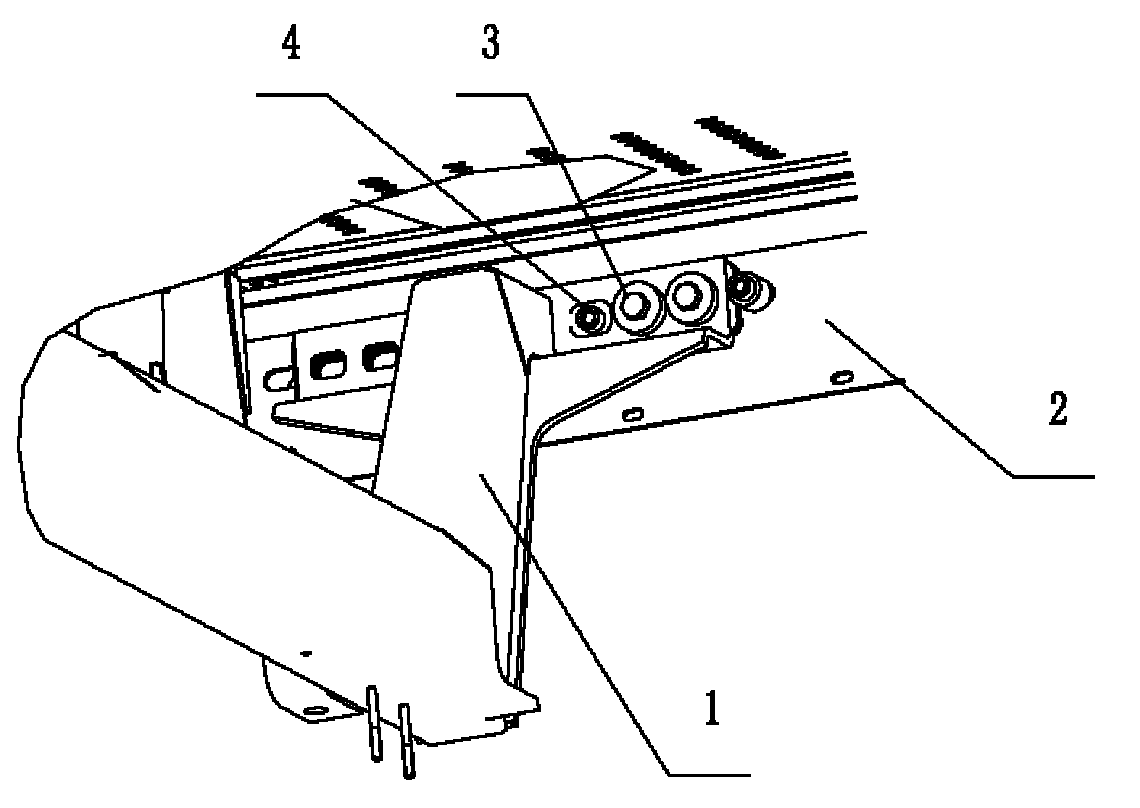
[0030] Example 1, such as figure 1 with figure 2 As shown, a coupling structure applied to high-speed rail vehicles, the coupling structure plays a role in coupling the equipment compartment of the underframe and the car body. specifically,

[0031] The connection structure mainly includes an installation beam 1 connecting the equipment compartment of the underframe.

[0032] The mounting beam 1 is fastened to the side beam 2 of the vehicle body underframe by a connecting bolt 3, and the connecting bolt 3 is applied with a tightening torque of 150-200 Nm on the side beam 2 of the vehicle body underframe.

[0033] A pad 5 with a thickness of 10 mm is lined between the installation beam 1 and the side beam 2 of the vehicle body underframe.

[0034] A safety bolt 4 is also fastened between the mounting beam 1 and the side beam 2 of the car body underframe. The safety bolt 4 is connected to the fixing plate 6 on the inner side of the side beam 2 of the car body underframe. The fixing pl...


PUM

PropertyMeasurementUnit
Thicknessaaaaaaaaaa

Abstract

The invention discloses a structure and a method for connecting an underframe equipment bay and a vehicle body. A bracket-free suspension way is adopted, the underframe equipment bay is supported by a static frictional force produced between an equipment bay mounting beam and a vehicle body underframe edge beam, an externally-protruded bracket is not required to be arranged on an vehicle body underframe, and the heavy equipment bay is arranged by a simplified positioning structure, so that difficulties in the design of rigidity and strength of the vehicle body underframe are reduced and the cost of parts of the vehicle body is reduced. The structure for connecting the underframe equipment bay and the vehicle body comprises the mounting beam connected with the underframe equipment bay, wherein the mounting beam is fastened on the vehicle body underframe edge beam by connecting bolts; the tightening torque of 150 to 200 Nm is applied to the connecting bolts on the vehicle body underframe edge beam; and a layer of base plate is backed between the mounting beam and the vehicle body underframe edge beam. The sufficient static frictional force is produced between the mounting beam and the vehicle body edge frame by applying the relatively higher tightening torque to the connecting bolts to support the underframe equipment bay.

Description

Technical field [0001] The invention relates to a connection structure and method between an underframe equipment compartment and a car body, specifically a connection structure and method without bracket suspension during the installation and positioning process of the underframe equipment compartment of a rail vehicle, and belongs to mechanical manufacturing field. Background technique [0002] At present, high-speed rail vehicles designed and used in China, such as urban light rail, subways, EMUs, and passenger trains, all have their undercarriage equipment compartments suspended and positioned by convex brackets on the underframe of the car body, supplemented by other tight Solid installation structure. [0003] The existing bracket type suspension positioning system and method require a certain amount of space for the bracket, and since the equipment compartment containing the equipment under the vehicle weighs about 10 tons, the bracket structure itself requires strict rigid...

Claims


Application Information

Patent Timeline
IPC IPC(8): B61D17/00
Inventor 王志春王红单宝珠李海虹
Owner BOMBARDIER SIFANG QINGDAO TRANSPORTATION
Features
  • R&D
  • Intellectual Property
  • Life Sciences
  • Materials
  • Tech Scout
  • Unparalleled Data Quality
  • Higher Quality Content
  • 60% Fewer Hallucinations
Learn More