Hair iron

A hair perm, hair clip technology, applied in the direction of curling or perming devices, hair curlers, hairdressing equipment, etc., can solve the problems of hair damage and high clamping pressure, and achieve the effect of inhibiting damage

Inactive Publication Date: 2011-05-11
PANASONIC CORP
View PDF4 Cites 2 Cited by
  • Summary
  • Abstract
  • Description
  • Claims
  • Application Information

AI Technical Summary

Problems solved by technology

With such a structure, when sliding on the clamped hair along the width direction of the clamping part, since the clamping force...

Method used


Image

  • Hair iron
  • Hair iron
  • Hair iron

Examples


Embodiment Construction

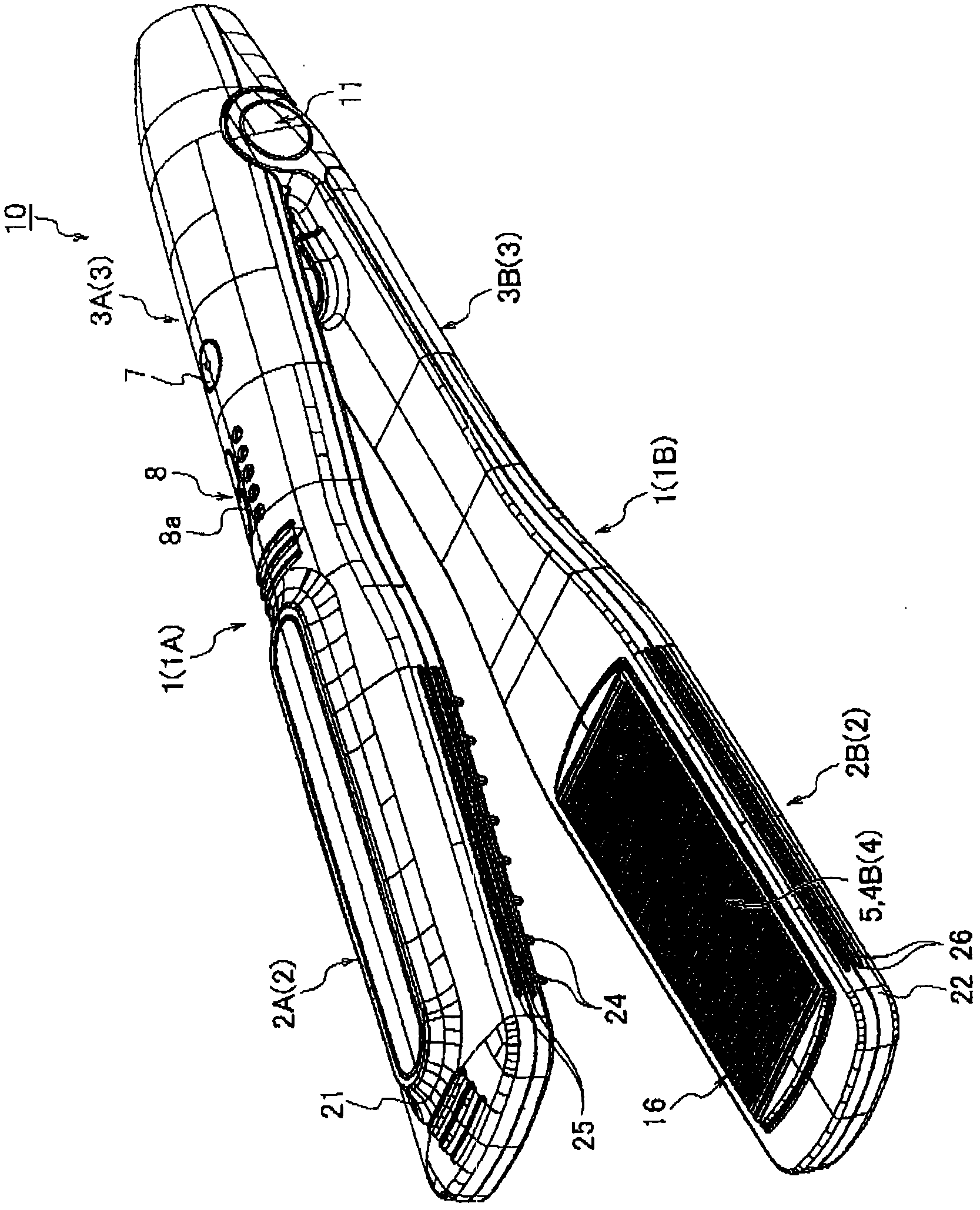
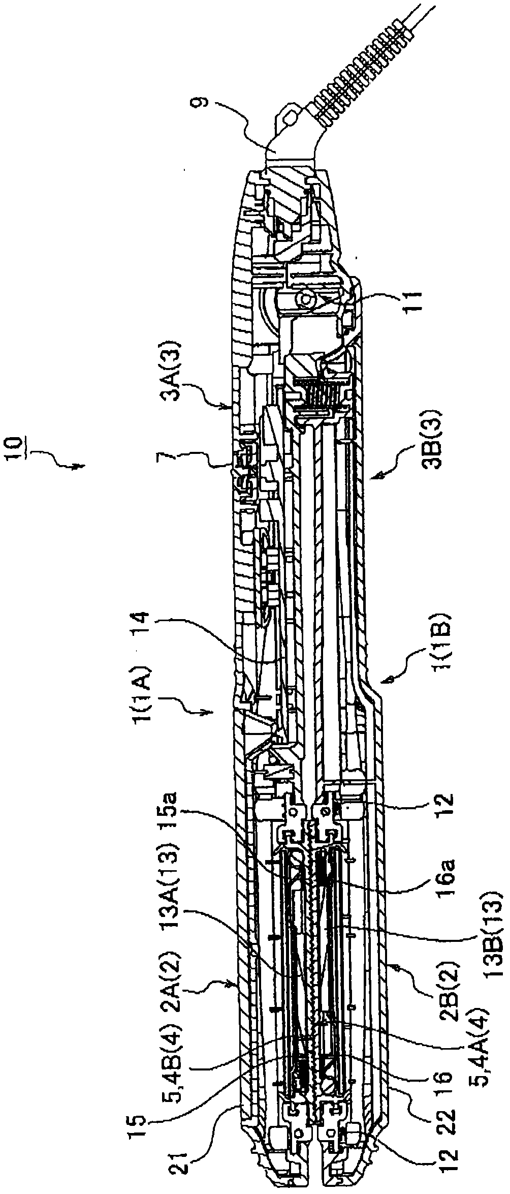
[0013] Hereinafter, embodiments of the present invention will be described in detail with reference to the drawings. In addition, in the following content, the up-down direction is defined based on the hair iron in the state where the first hair clamping surface and the second hair clamping surface are in contact with each other and the second hair clamping surface faces upward. In addition, the clip part side of the hair iron will be described as the front, and the grip part side will be described as the rear.

[0014] Figure 1 ~ Figure 3 It is a figure which shows one Embodiment of the hair iron of this invention. Such as figure 1 and figure 2 As shown, the hair iron 10 of this embodiment includes a pair of arms 1, the clamping part 2 having the hair clamping surface 4 for clamping the hair is disposed on the front end side of the pair of arms 1, and the clamping part 2 is disposed on the base end side of the pair of arms 1. The grip part 3 held by the user.

[0015] ...


PUM


Abstract

A hair iron includes an upper first clip portion (2A) having an upper first hair clip surface (4A), and a lower second clip portion (2B) having a lower second hair clip surface (4B). In this hair iron, when the hair clip surfaces (4A and 4B) are brought into contact with each other in a state of not clipping hair (H) therebetween, space portions (6) are formed between these upper and lower hair clip surfaces (4A and 4B).

Description

technical field [0001] The present invention relates to hair irons. Background technique [0002] At present, there is known a hair iron such as that disclosed in Japanese Patent Application Laid-Open No. 11-32831, which is provided with a clamping portion (pressing portion) having a pair of hair clamping surfaces (replacement parts) arranged opposite to each other, and along the Wavy portions are provided in the width direction of the pair of hair clamping surfaces, and the hair is trimmed by sandwiching the hair between the wavelike portions. [0003] However, in the above-mentioned conventional hair iron, a structure is formed in which the corrugated portions of the pair of hair holding surfaces are fitted and meshed with each other. With such a structure, when sliding on the clamped hair along the width direction of the clamping part, since the clamping force of the clamped hair is high, an excessive (more than necessary) frictional force may act on the hair surface, th...

Claims


Application Information

Patent Timeline
IPC IPC(8): A45D1/04
CPCA45D1/02A45D1/04A45D2/001
Inventor 仲宗根英俊山崎直树
Owner PANASONIC CORP
Why Eureka
Try Eureka