Electronic device with adjustable panel inclination angle

An electronic device and a tilt angle technology, which is applied to the field of electronic devices with adjustable panel tilt angle, can solve the problems that the front panel cannot be rotated left and right and tilted up and down at the same time, and the visibility can not be reduced. Low, easy-to-operate effect

Inactive Publication Date: 2014-07-16
PANASONIC AUTOMOTIVE SYST DEV TIANJIN
View PDF8 Cites 0 Cited by
  • Summary
  • Abstract
  • Description
  • Claims
  • Application Information

AI Technical Summary

Problems solved by technology

However, neither of them can realize the left and right rotation and up and down tilting of the front panel at the same time, so that the problems of reduced visibility due to reflection cannot be solved.

Method used


Image

  • Electronic device with adjustable panel inclination angle
  • Electronic device with adjustable panel inclination angle
  • Electronic device with adjustable panel inclination angle

Examples


no. 2 example

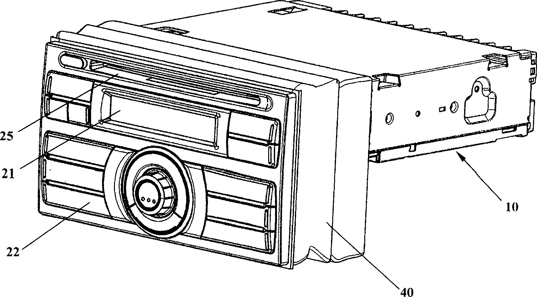
[0072] Such as Figure 6 As shown, the electronic device with an adjustable panel inclination angle includes: a main body 210 , a front panel 220 , and a support plate 230 . The basic structure of this embodiment is the same as that of the first embodiment, and only the differences between this embodiment and the first embodiment will be described below.

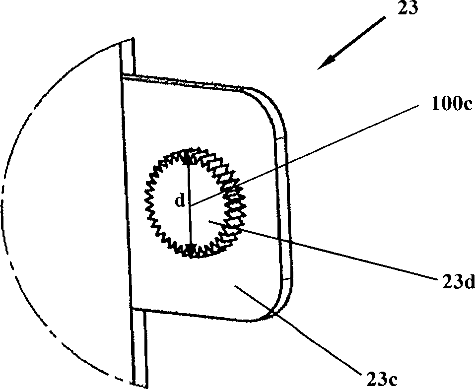
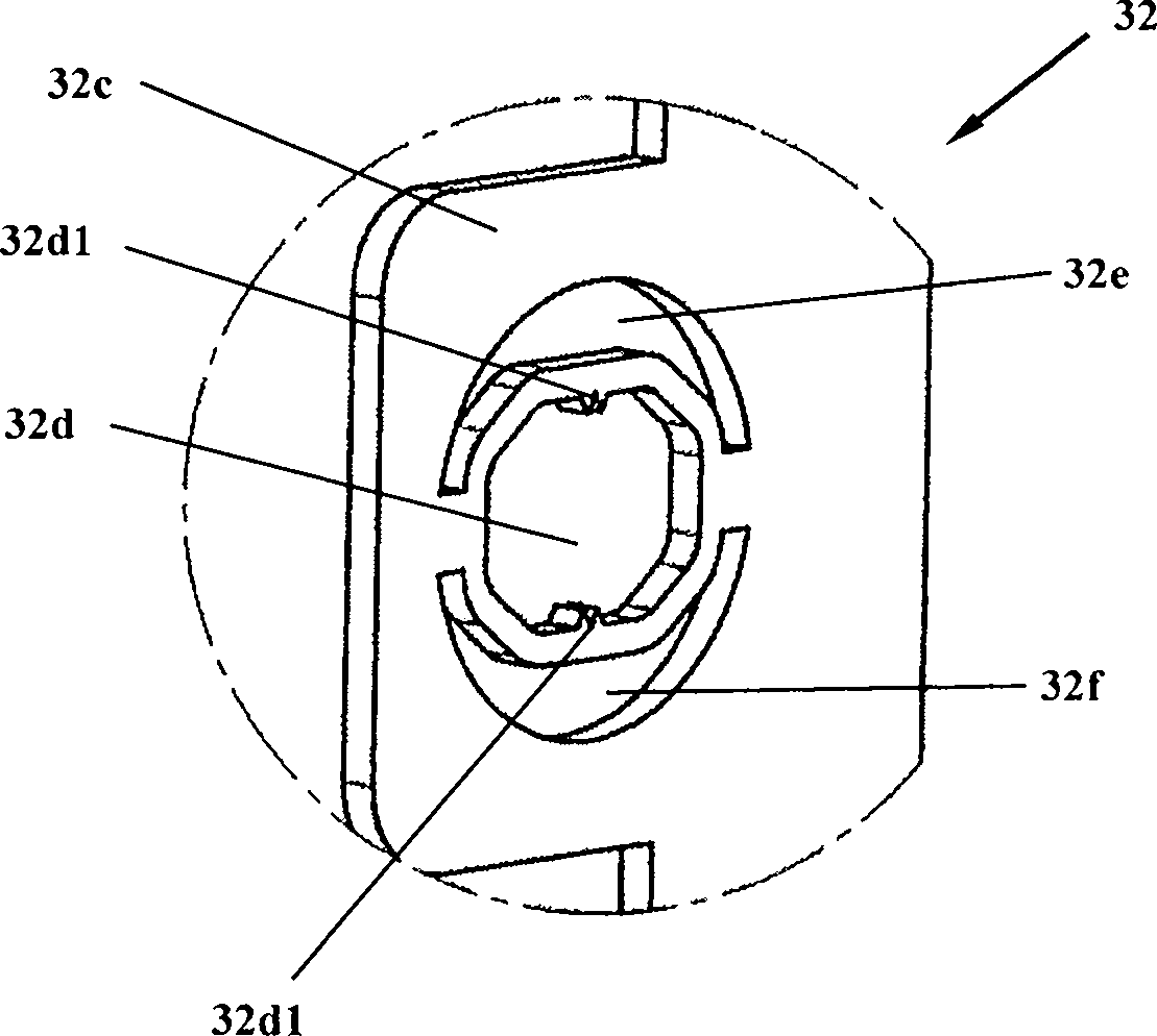
[0073] Such as Figure 6 As shown, the second connection part 223 ( Figure 6 223L, 223R) have the same structure as the fourth connection portion 32 of the first embodiment. The two second connection parts 223 are disposed on the back side of the front panel 220 , ie, the side facing the support plate 230 , and near the central area of ​​the front panel 220 . The rotation centers 100c of the two second connection parts 223 are aligned in the horizontal direction.

[0074] Figure 7A and Figure 7B They are respectively a schematic side view and a schematic top view of the electronic device with an adjustable panel inc...

no. 3 example

[0094] Figure 10A It is an exploded top view diagram of the first connection part and the third connection part of the electronic device with adjustable panel inclination angle according to the third embodiment of the present invention. Figure 10B It is a schematic plan view of the combination of the first connection part and the third connection part of the electronic device with an adjustable panel inclination angle according to the third embodiment of the present invention. Such as Figure 10A As shown, the electronic device with an adjustable panel inclination angle includes a main body 310 , a front panel 20 (not shown), and a support plate 330 . The basic structure of this embodiment is the same as that of the first embodiment, and only the differences between this embodiment and the first embodiment will be described below.

[0095] The body part 310 includes the body 11 but does not include the connection plate. The two first connecting parts 313 are symmetrically...


PUM


Abstract

The invention provides an electronic device with an adjustable panel inclination angle, which comprises a body part, a front panel and a supporting plate, wherein the body part is used for accommodating a circuit base plate and provided with a first connecting part; the front panel is electrically connected with the body part and provided with a second connecting part arranged at one side of the front panel, which is close to the body part; the supporting plate is arranged between the body part and the front panel and provided with a third connecting part and a fourth connecting part; under the action of a first action force from the front panel, the second connecting part rotates around a first center line passing through a rotating center of the second connecting part, so that the front panel rotates with a first angle; and under the action of a second action force from the front panel, the third connecting part rotates around the second center line passing through a rotating center of the third connecting part, so that the front panel and the supporting plate rotate with a second angle, the first center line is vertical to the second center line mutually, and the first center line and the second center line are respectively parallel to a second surface.

Description

technical field [0001] The invention relates to an electronic device, in particular to an electronic device with an adjustable panel inclination angle. Background technique [0002] Generally, a center console is arranged in front of a driver's seat of a vehicle, and a vehicle instrument, an operation unit, and the like are provided in the center console. In addition, with the rapid development of electronic technology, in-vehicle electronic devices such as car stereos and navigators are added, and the operation parts of these electronic devices are usually arranged on the above-mentioned central control panel. [0003] Japanese Patent Laying-Open No. 9-138654 discloses a device capable of adjusting the inclination and rotation angle of the display panel (such as Figure 11 As shown), the connecting part 923 rotatably connects the supporting part 930 and the display panel 920, and the user pushes and pulls the upper part of the display panel 920 to make the ball 923d in the ...

Claims


Application Information

Patent Timeline
Patent Type & Authority Patents(China)
IPC IPC(8): B60R11/02G09F9/00
Inventor 曾伟
Owner PANASONIC AUTOMOTIVE SYST DEV TIANJIN
Why Eureka
Try Eureka