Hydraulic dynamic brake operating system for tractor

A dynamic braking and control system technology, applied in the field of tractors, can solve the problem that the braking pressure cannot meet the braking requirements of the whole vehicle, and achieve the effect of satisfying the braking performance and rigorous system structure

Active Publication Date: 2011-05-11
FIRST TRACTOR
View PDF6 Cites 9 Cited by
  • Summary
  • Abstract
  • Description
  • Claims
  • Application Information

AI Technical Summary

Problems solved by technology

With the continuous increase of the power section of the tractor, the weight of the whole vehicle is also increasing, and the braking pressure of the existing device can no longer meet the braking requirements of the whole vehicle.

Method used


Image

  • Hydraulic dynamic brake operating system for tractor
  • Hydraulic dynamic brake operating system for tractor
  • Hydraulic dynamic brake operating system for tractor

Examples


Embodiment Construction

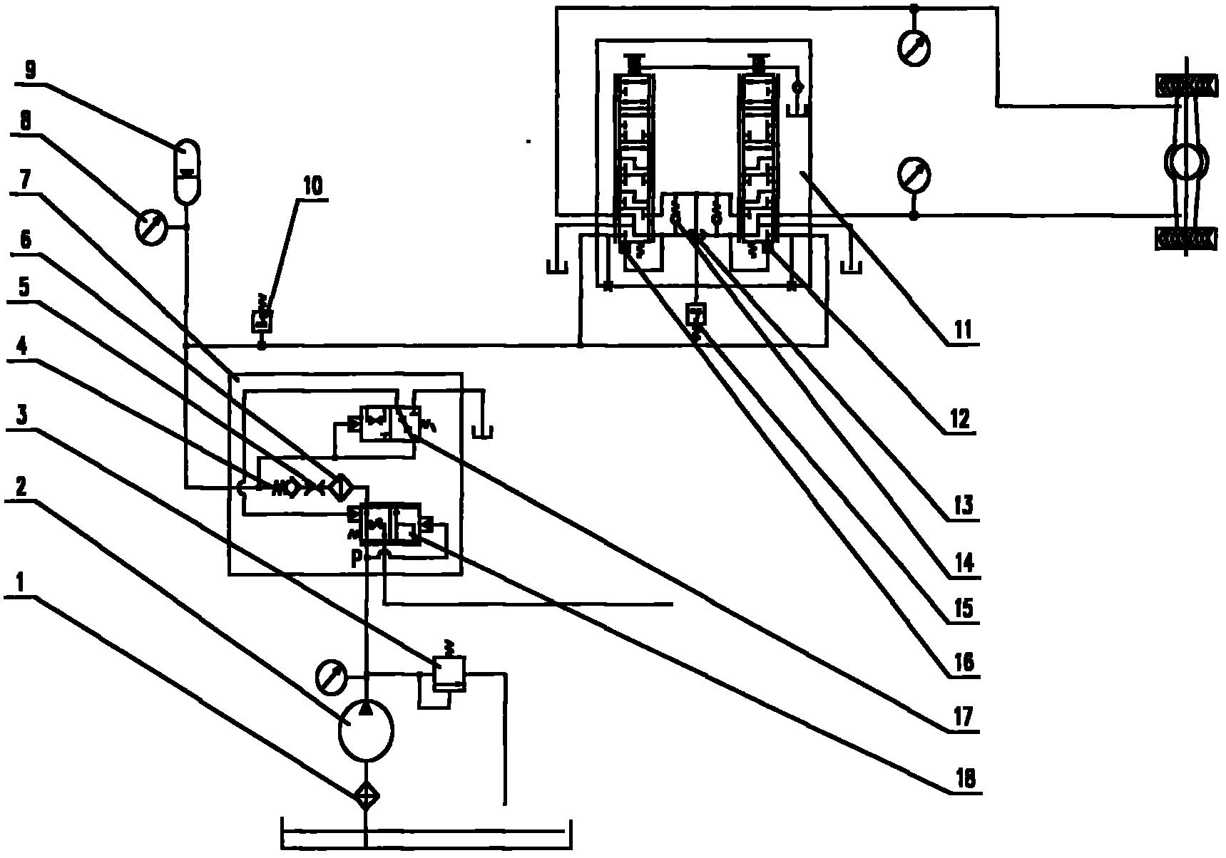
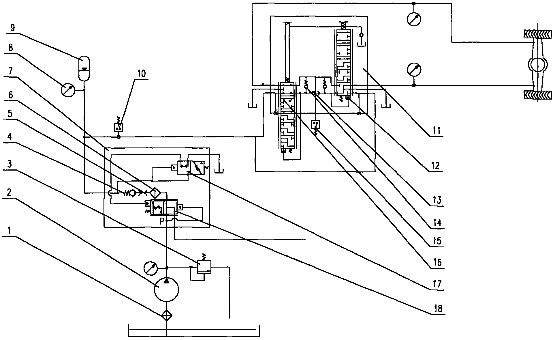
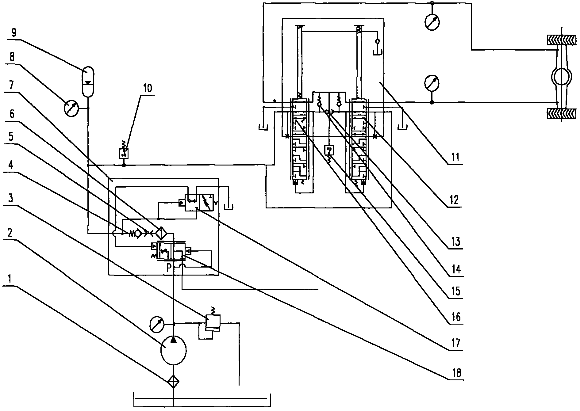
[0012] The present invention will be further described below in conjunction with the accompanying drawings. like Figure 1~3 As shown, the tractor hydraulic power brake control system mainly includes oil suction filter 1, oil pump 2, overflow valve 3, check valve 4, throttle port 5, high pressure oil filter 6, liquid filling valve 7, Pressure gauge 8, accumulator 9, brake low pressure alarm switch 10, dual power brake valve 11, left power brake valve 12, shuttle valve 13, one-way valve 14, brake tail light pressure switch 15, right power brake Actuated valve 16, pressure setting part 17, pressure compensator 18; Oil suction oil filter 1 is contained in the oil tank of tractor, and oil pump 2 is installed on one side of tractor; Oil suction oil filter 1 and oil pump 2 are connected by oil pipe. The filling valve 7 is installed on one side of the tractor and connected to the oil pump 2 through a pipeline; the dual power brake valve 11 is installed on the cab floor, and the dual...


PUM


Abstract

The invention discloses a hydraulic dynamic brake operating system for a tractor. The hydraulic dynamic brake operating system mainly comprises an oil suction filter, an oil pump, an overflow valve, a check valve 1, a throttling port, a high-pressure oil filter, a liquid filling valve, a pressure gauge, an accumulator, a brake low pressure alarming switch, a dual-circuit dynamic brake valve, a left dynamic brake valve, a shuttle valve, a check valve 2, a brake taillight pressure switch, a right dynamic brake valve, a pressure setting piece and a pressure compensator. The hydraulic dynamic brake operating system is characterized in that the oil suction filter is arranged in an oil tank of the tractor; the oil pump is arranged on one side of the tractor; the oil suction filter is connected with the oil pump through an oil pipe; the liquid filling valve is arranged on one side of the tractor, and is connected with the oil pump through a pipeline; and the dual-circuit dynamic brake valve is mounted on the bottom plate of a driving cab, and is connected with the liquid filling valve through an oil pipe. The system eliminates other pumping sources by dint of the hydraulic steering system of the tractor, and fully meets the requirements on the brake of the whole tractor and the braking performance of a high-power tractor. The structure of the system is compact and meticulous.

Description

technical field [0001] The invention belongs to the field of tractors, and relates to a hydraulic power braking control system for tractors. Background technique [0002] At present, on the high-power wheeled tractors produced in my country, most of the braking systems are hydraulic manpower control. It pumps the hydraulic oil in the brake pump into the brake through the pressure exerted by the operator on the pedal to make the tractor brake. Since the operator's pedaling force is limited, the oil pressure transmitted to the brake is also limited. With the continuous increase of the power range of the tractor, the weight of the whole vehicle is also increasing, and the braking pressure of the existing device can no longer meet the braking requirements of the whole vehicle. [0003] In order to meet the ever-increasing demand for tractor power, there must be a matching brake control system that can satisfy all the braking performance of the whole machine. Contents of the ...

Claims


Application Information

Patent Timeline
Patent Type & Authority Applications(China)
IPC IPC(8): B60T13/128B62D5/07B60Q1/44
Inventor 刘涛王巧灵张凯王红杨婉丽张璐
Owner FIRST TRACTOR
Why Eureka
Try Eureka