
Projector

A technology for projectors and projections, which is applied in the field of projectors, and can solve problems such as inability to improve convenience and difficulty in operating the legs

Inactive Publication Date: 2011-05-11
SEIKO EPSON CORP
View PDF8 Cites 6 Cited by
  • Summary
  • Abstract
  • Description
  • Claims
  • Application Information

AI Technical Summary

Problems solved by technology

Therefore, it is difficult to operate the leg portion, and there is a problem that convenience cannot be improved.

Method used


Image

  • Projector
  • Projector
  • Projector

Examples


Embodiment Construction

[0035] Hereinafter, one embodiment of the present invention will be described based on the drawings.

[0036] (Appearance composition)

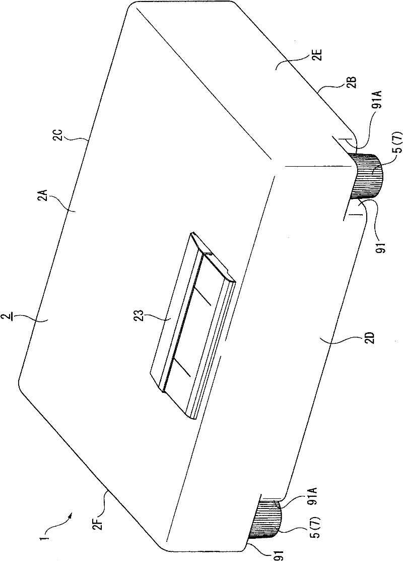
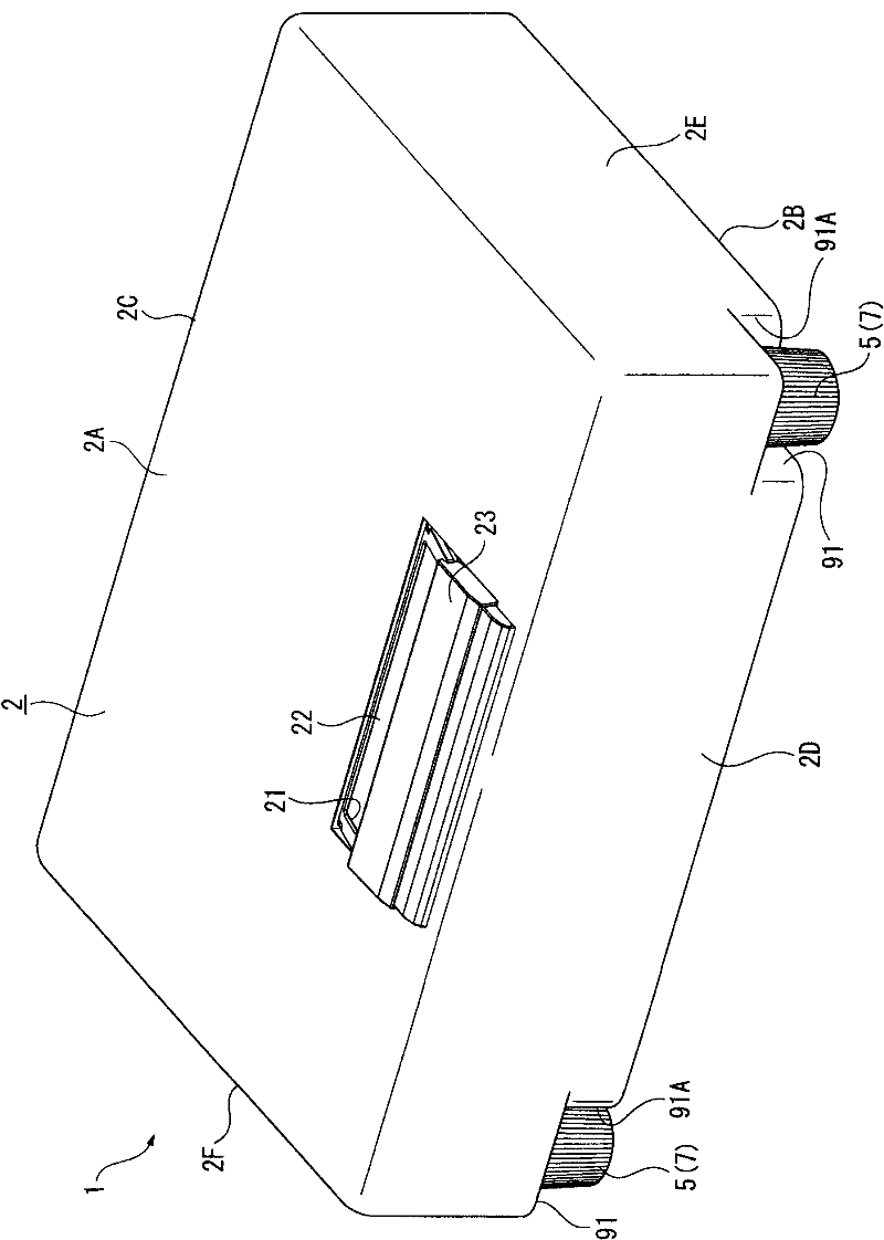
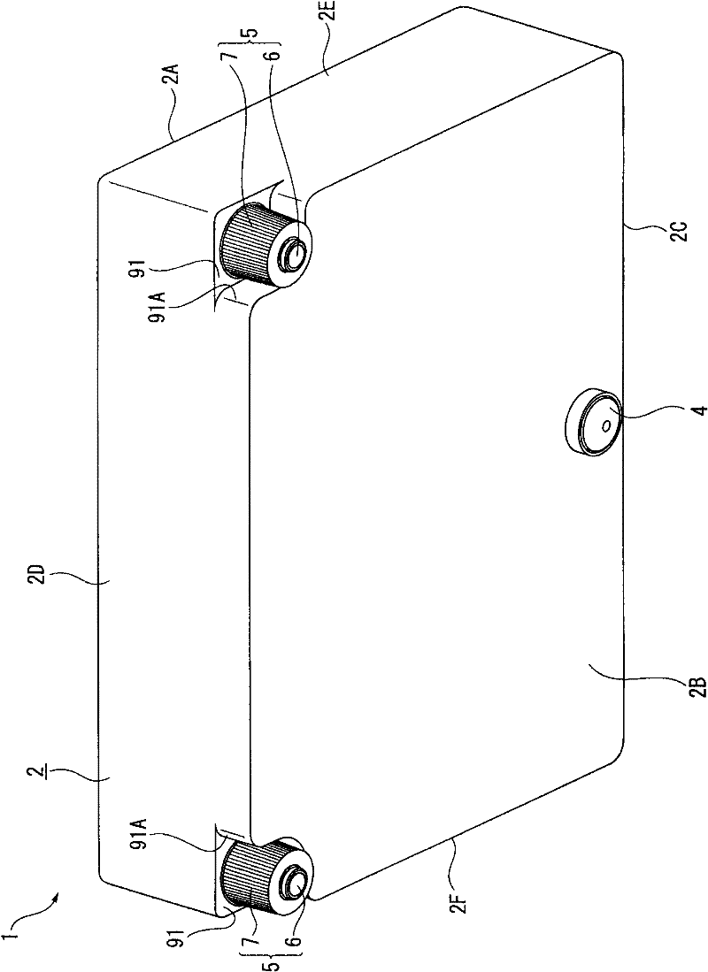
[0037] figure 1 and figure 2 is a diagram schematically showing a schematic configuration of the projector 1 . specifically, figure 1 It is a perspective view of a state in which the protective cover 23 is located at the closed position as seen from the upper back side, figure 2 It is a perspective view of the state where the protective cover 23 is located in the non-closed position as seen from the upper back side.

[0038] In addition, "upper" and "lower" described below are used in figure 1 or figure 2 Equivalent to up and down in the drawing view of . In addition, in the following, for convenience of description, the projection direction side is referred to as the front ( figure 1 , figure 2 middle depth side), and the opposite side of the projection direction as the back side ( figure 1 , figure 2 near the front).

[003...


PUM


Abstract

The invention provides a projector with easily operated foot and improved convenience. A projector includes: an outer housing which forms an external case; and a foot attached to the outer housing and brought into contact with an installation surface when the projector is placed on the installation surface, wherein the foot includes a foot main body which contacts the installation surface, and a rotational member supported rotatably with respect to the outer housing in such a condition that at least a part of the rotational member is exposed to the outside of the outer housing, and the foot main body engages with the rotational member and shifts in the direction along a rotation axis of the rotational member in accordance with rotation of the rotational member.

Description

technical field [0001] The present invention relates to projectors. Background technique [0002] Conventionally, as a projector, there is known a structure having a leg portion (foot portion) (see, for example, Patent Document 1) provided on the bottom surface of an exterior case, and when the projector is placed on a desk or the like When placed on the mounting surface, it abuts against the mounting surface. [0003] The leg portion described in Patent Document 1 is configured to be rotatable with respect to the exterior case by a screw mechanism, and the protrusion length from the bottom surface of the exterior case is changed by the rotation. [0004] In addition, the user can change the protruding length from the bottom surface of the exterior case by rotating the leg portion, thereby changing the posture of the projector placed on the mounting surface and projecting an image from the projector to the screen. suitable location. [0005] Patent Document 1: Japanese Pa...

Claims


Application Information

Patent Timeline
Patent Type & Authority Applications(China)
IPC IPC(8): G03B21/54G03B21/00
CPCG03B21/54G03B21/145
Inventor 关茂行
Owner SEIKO EPSON CORP
Learn More