Vibration actuator

一种振动致动器、振动方向的技术,应用在电气元件、机电装置等方向,能够解决耐冲击性低、构造复杂化等问题,达到提高耐跌落冲击性、实现薄型化的效果

Inactive Publication Date: 2011-05-11
COPAL CO LTD
View PDF7 Cites 40 Cited by
  • Summary
  • Abstract
  • Description
  • Claims
  • Application Information

AI Technical Summary

Problems solved by technology

Therefore, the possibility that the yoke will violently collide with the frame due to the impact of the drop is high, so it can be said that the shock resistance of the structure of the vibration actuator is low, and various methods for alleviating the impact of the yoke on the frame are required. Countermeasures, so there is a problem of complicating the structure

Method used


Image

  • Vibration actuator
  • Vibration actuator
  • Vibration actuator

Examples


Embodiment Construction

[0048] Hereinafter, preferred embodiments of the vibration actuator of the present invention will be described in detail with reference to the drawings.

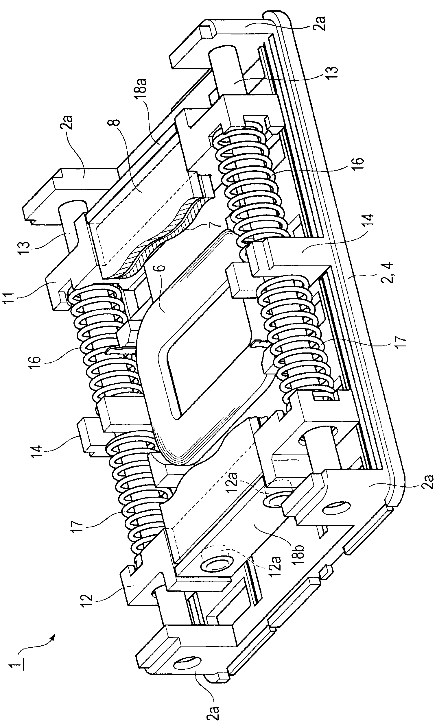
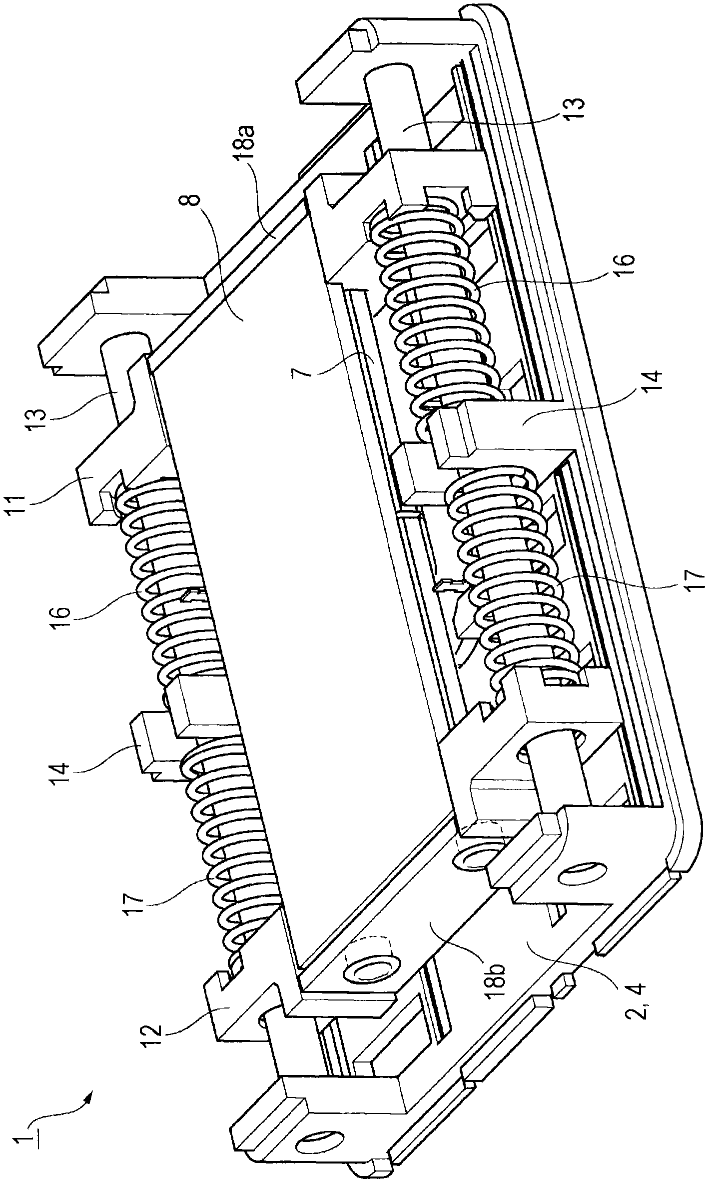
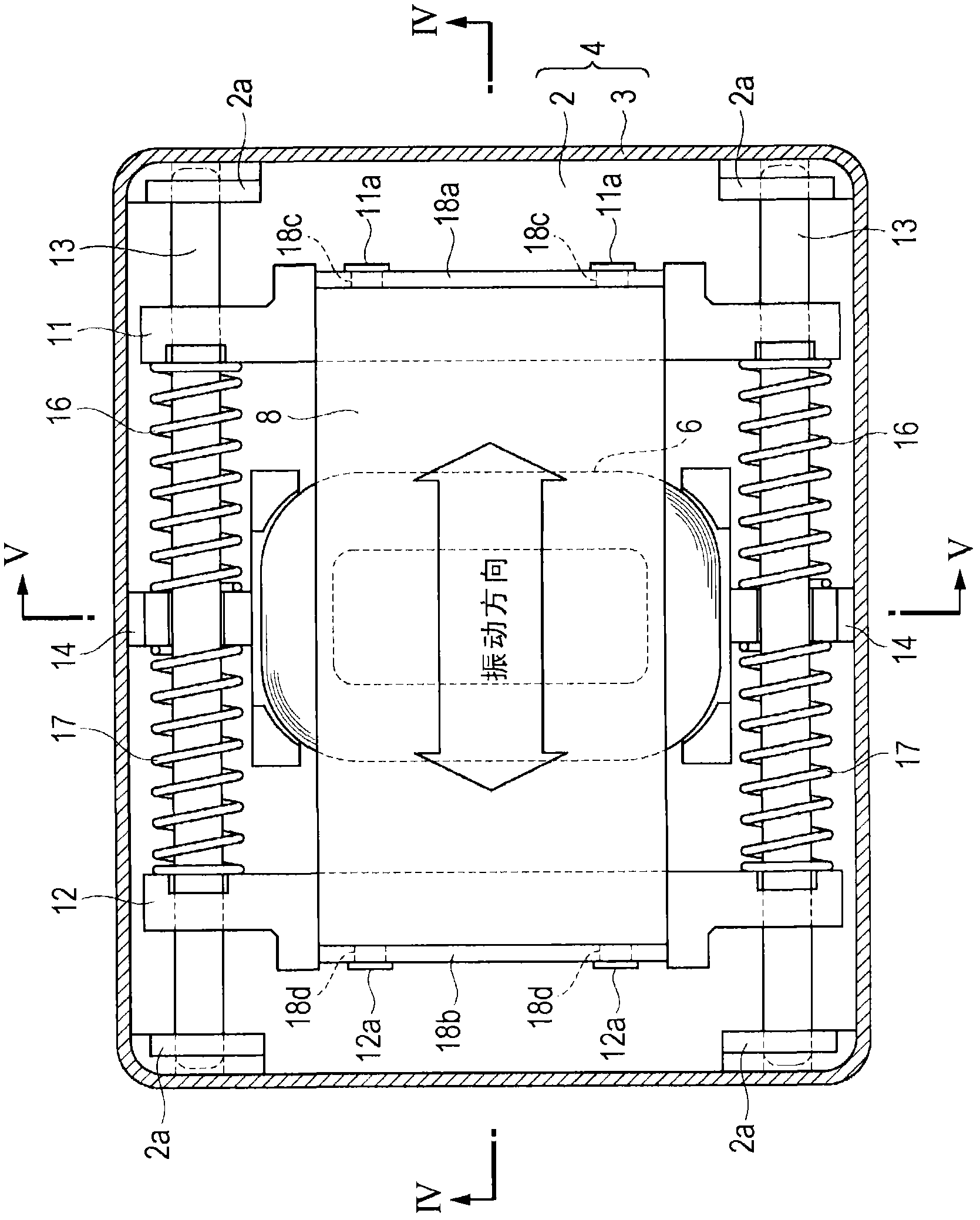
[0049] Such as Figure 1 to Figure 5 As shown, the vibration actuator 1 has a flat frame 4 including a base plate 2 and a cover 3 . Inside the housing 4 are accommodated an annular flat coil 6 fixed to the base plate 2 and a plate-shaped flat magnet 7 arranged to face the coil 6 . The magnet 7 is formed by two magnet parts 7a and 7b whose one plane side is an N pole and the other plane side is an S pole. The magnet 7 is configured such that the N pole of one magnet portion 7a faces the S pole of the other magnet portion 7b on a plane, and the side surface of the magnet portion 7a and the side surface of the magnet portion 7b are bonded together with an adhesive. . Furthermore, the magnet 7 may be formed by magnetizing one magnetic plate.

[0050] Furthermore, the coil 6 is connected to the terminal electrode 5 provided o...


PUM


Abstract

A vibration actuator includes a coil that extends in a vibration direction and has a flat shape and a magnet that extends in the vibration direction and has a flat shape, so that a case can be made flat or low profile. A weight portion is supported by a shaft, so that, when a drop impact is applied, the weight portion can move along the shaft and the weight portion is not freely moved in the case. A coil spring is disposed between a spring receiving portion and a weight portion. Therefore there is no unnecessary space in the case, so that space can be saved and the vibration actuator can be made compact.

Description

technical field [0001] The present invention relates to a small vibration actuator that is used as a vibration generating source for notifying a user of an incoming call of a portable wireless device such as a mobile phone, or for transmitting the operating feeling of a touch panel or the presence of an amusement machine to a mobile phone. Finger or hand vibration generation source, etc. Background technique [0002] Conventionally, there is Japanese Patent Application Laid-Open No. 10-117472 as a technology in this field. the bulletin figure 1 The disclosed vibration actuator has a frame body in which a soft elastic body is fixed, and a cylindrical yoke made of a magnetic body is arranged in the frame body. The yoke also serves as a vibration-generating weight, and is supported by a leaf spring within the housing. The leaf spring is fixed to a plate-shaped first elastic body that closes the opening of the housing, and has a spiral-like shape with a convex center. In add...

Claims


Application Information

Patent Timeline
Patent Type & Authority Applications(China)
IPC IPC(8): H02K33/18H02K33/02
CPCH02K33/16
Inventor 小田岛慎生川昇殿贝佳英山胁隆太保科智昭
Owner COPAL CO LTD
Why Eureka
Try Eureka