
Cuter for milling high-quality plate edges and processing method thereof

A quality, milling cutter technology, applied in milling cutters, metal processing equipment, manufacturing tools, etc., can solve the problem of insufficient quality of the edge of the board, and achieve the effect of flat edge of the board

Active Publication Date: 2011-05-18
SHENZHEN JINZHOU PRECISION TECH
View PDF5 Cites 4 Cited by
  • Summary
  • Abstract
  • Description
  • Claims
  • Application Information

AI Technical Summary

Problems solved by technology

[0004] For the above-mentioned conventional milling cutters, since the cutting grooves and broken tooth grooves are symmetrically distributed along the cutter head according to certain rules, the cutting edges are also regularly symmetrically distributed. When performing plate milling operations, the movement of the cutting edge and teeth of the milling cutter also has certain rules. Cooperating with the milling machine spindle speed and feed speed, it may cause regular ripples on the edge of the milled plate instead of Flat board edge, resulting in insufficient quality of the board edge

Method used


Image

  • Cuter for milling high-quality plate edges and processing method thereof
  • Cuter for milling high-quality plate edges and processing method thereof
  • Cuter for milling high-quality plate edges and processing method thereof

Examples


Embodiment 1

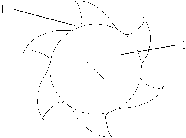
[0037] The structure of the milling cutter is like image 3 and Figure 4 As shown, the cutting groove is a right-handed groove, the broken tooth groove is a left-handed groove; the chaotic tooth groove is also a right-handed groove.

[0038] Among them, the helix angle of the cutting groove can generally be between 15° and 35°, the helix angle of the broken tooth groove can generally be between -15° and -35°, and the helix angle of the chaotic tooth groove The angle can be between 65° and 89°, more precisely, between (the spiral angle of the cutting groove +45°) and 89°. At the same time, it is necessary to ensure that the angle of the spiral angle with the broken tooth groove deviates by 10 ° above. The deviation of the helix angle from the broken tooth groove is to avoid the same trend of the chaotic tooth groove and the broken tooth groove, otherwise the effect of destroying the regular uniform distribution of the original cutting edge teeth will not be well achieved. The gre...

Embodiment 2

[0041] The structure of the milling cutter is like Figure 5 As shown, the cutting groove is a right-handed groove, and the tooth groove is a left-handed groove; the chaotic tooth groove is also a left-handed groove.

[0042] The helix angle of the left-handed chaotic tooth groove can be selected in a larger range, and the design freedom of the number of bars is also large. Among them, the helix angle of the cutting groove can generally be between 15° and 35°, the helix angle of the broken tooth groove can generally be between -15° and -35°, and the helix angle of the chaotic tooth groove The angle can be between -15°~-89°, more precisely, between (the helix angle of the cutting groove -45°)~-89°. At the same time, it is necessary to ensure the helix angle of the broken tooth groove. The angle deviates by more than 10°. The deviation of the helix angle from the broken tooth groove is to avoid the same trend of the chaotic tooth groove and the broken tooth groove, otherwise the e...

Embodiment 3

[0045] The structure of the milling cutter is like Image 6 As shown, the cutting groove is a right-handed groove, and the broken tooth groove is a right-handed groove; the chaotic tooth groove is also a right-handed groove.

[0046] Wherein, the helix angle of the cutting groove may generally be between 15° and 35°, and the helix angle of the broken tooth groove may generally be between (the helix angle of the cutting groove + 45°) and 89°, The helix angle of the chaotic tooth groove can be between 65° and 89°, more specifically, between (the angle of the helix angle of the cutting groove + 45°) and 89°. At the same time, it is necessary to ensure that the tooth groove is The angle of the helix angle deviates more than 10°. The deviation of the helix angle from the broken tooth groove is to avoid the same trend of the chaotic tooth groove and the broken tooth groove, otherwise the effect of destroying the regular uniform distribution of the original cutting edge teeth will not b...


PUM

PropertyMeasurementUnit
Angleaaaaaaaaaa

Abstract

The invention discloses a cutter for milling high-quality plate edges and a processing method thereof. A set of spiral cutting slots and a set of spiral tooth breaking slots are arranged on a cutter head of the cutter for milling high-quality plate edges, wherein the spiral cutting slots are used for forming cutting edges, and the spiral tooth breaking slots are crossed with the cutting slots andused for breaking the cutting slots to form edge teeth; and a set of spiral tooth disordering slots respectively crossed with the cutting slots and the tooth breaking slots are also arranged on the cutter head. The cutter for milling high-quality plate edges in the invention is additionally provided with one set of tooth disordering slots, the spiral angles of the tooth disordering slots are different from the spiral angles of the cutting slots and the tooth breaking slots, the tooth disordering slots pass through the edge teeth formed by the cutting slots and the tooth breaking slots to formnew irregular tooth slots on the passed edge teeth ,and the regular and uniform distribution of the original cutting edge teeth is destroyed so that many cutting edges are not symmetrical any more. As the regularity of the edge teeth on the cutting edges of the milling cutter is destroyed by the tooth disordering slots, no periodical regularity exists when a plate is milled and cut so that the milled plate edges are flat without corrugations.

Description

Technical field [0001] The present invention relates to the technical field of milling cutter processing, and more specifically, to a milling cutter with high edge quality and a processing method thereof. Background technique [0002] At present, the head part of a conventional milling cutter is usually formed by two sets of spiral grooves. One group of spiral grooves are cutting grooves that form the cutting edge, and the other group of spiral grooves are tooth-broken grooves. The tooth-broken grooves intersect with the cutting grooves, which are used to break the cutting grooves and form cutting edges, making the cutting part sharper and cutting chips more sharp. Broken, easier to discharge. [0003] For a right-handed milling cutter, the cutting groove is a right-handed spiral groove, and the broken tooth groove can be the same direction as the cutting groove, that is, the same right-handed spiral groove, or it can be opposite to the cutting groove, that is It is a left-handed...

Claims


Application Information

Patent Timeline
IPC IPC(8): B23C5/10
Inventor 屈建国厉学广
Owner SHENZHEN JINZHOU PRECISION TECH
Learn More