drive unit

A driving device and actuating mechanism technology, applied in the direction of valve devices, engine components, machines/engines, etc., can solve the problems of inaccurate adjustment, inability to adjust the opening and closing phase and stroke of intake and exhaust valves, and achieve small structural changes , Continuous adjustment of the valve switch phase and opening stroke, the effect of large adjustment ability

Active Publication Date: 2017-08-25
杨鲁川
View PDF3 Cites 0 Cited by
  • Summary
  • Abstract
  • Description
  • Claims
  • Application Information

AI Technical Summary

Problems solved by technology

But the shortcoming of this device is the same as the above-mentioned shortcoming in the prior art, all can not make bigger adjustment to the opening and closing phase and stroke of intake and exhaust valve, also can't it be adjusted accurately

Method used


Image

  • drive unit
  • drive unit
  • drive unit

Examples


Embodiment Construction

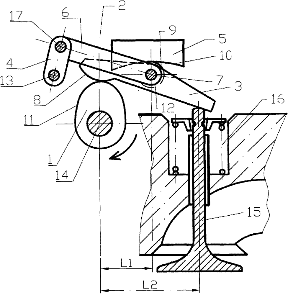
[0024] figure 1 An embodiment of the drive device according to the invention is schematically represented. Such a drive is used in particular to drive the movement of a cylinder valve stem of an internal combustion engine. In this embodiment, the internal combustion engine cylinder refers especially to the internal combustion engine cylinder of a motorcycle. This cylinder is characterized by its compact structure and small installation space.

[0025] Such as figure 1 As shown, in this embodiment, the driving device has a cam 1 mounted on a cam drive shaft 14 . The cam drive shaft 14 is driven by other power devices, thereby driving the cam 1 to rotate. The above-mentioned power plant is not shown in the figure.

[0026] What cooperates with cam 1 is a rocking arm 3. In this embodiment, the rocker arm 3 is a strip-shaped plate-like member. The rocker arm 3 extends relatively long in the horizontal direction in the figure, and relatively narrow in the vertical direction....


PUM


Abstract

A valve drive mechanism includes a cam (1), a rocker arm (3) driven by the cam and supported on a bearing shaft (7), and an actuator (2) for adjusting the position of the rocker arm. The actuator comprises at least a link lever (6) which is hinged at one end to the middle part of the rocker arm via the bearing shaft; a crank (4) which is connected at one end to the other end of the link lever, and hinged at the other end on a bearing pin (13); and a guiding support body (5) with a curve surface (10). The hinge portion of the link lever and the rocker arm is movably supported on the guiding support body. The drive mechanism can adjust the opening lift of intake / exhaust valve for an internal combustion engine by the actuator, thereby the ability for adjusting the intake / exhaust valve can be improved.

Description

technical field [0001] The invention relates to a driving device, in particular to a driving device for opening and closing an intake and exhaust valve of an internal combustion engine, especially a driving device for opening and closing an intake and exhaust valve of an internal combustion engine of a motorcycle and a miniature automobile. Background technique [0002] European patent EP 1 672 183 A1 discloses a rocker arm for positively controlling a valve arrangement. Wherein, one end of the rocker arm is connected with an adjustment device, and a part of the adjustment device can be stretched out so as to adjust the position of the end of the rocker arm. A rocking arm roller is arranged at the middle part of the rocking arm, and the shaft of the roller is connected with the supporting shaft of the roller wrapped on the outer circumference of the cam through a connecting piece. However, the adjustment of the opening stroke of the valve by this forced control device is li...

Claims


Application Information

Patent Timeline
Patent Type & Authority Patents(China)
IPC IPC(8): F01L13/00F01L1/18F01L1/30
CPCF01L1/182F01L13/0021F01L2001/188F01L2305/00
Inventor 杨鲁川
Owner 杨鲁川
Why Eureka
Try Eureka