Continuous variable valve lift device and control method thereof

A valve lift, variable technology, used in valve devices, engine control, internal combustion piston engines, etc., can solve the problems of complex structure, poor lubrication conditions, large assembly errors, etc. simple effect

Active Publication Date: 2011-09-21
CHERY AUTOMOBILE CO LTD
View PDF0 Cites 0 Cited by
  • Summary
  • Abstract
  • Description
  • Claims
  • Application Information

AI Technical Summary

Problems solved by technology

Most of the patents related to this field are from Japan and the United States, and there are more and more engine products applying this technology, but most of the variable valve lift devices used in existing patents or products are two-stage variable lift, That is, the two states of high valve lift and low valve lift cannot meet the needs of the valve opening height under various engine working conditions
Most of the few existing valve lift continuously variable devices have complex structures, poor lubrication conditions, high manufacturing costs, and large assembly errors; Requirements for miniaturization of the engine and the layout of the engine in the vehicle; at the same time, because of the complexity of the mechanism, the noise generated will also be large

Method used


Image

  • Continuous variable valve lift device and control method thereof
  • Continuous variable valve lift device and control method thereof
  • Continuous variable valve lift device and control method thereof

Examples


Embodiment Construction

[0030] Below with reference to the accompanying drawings, through the description of the embodiments, the specific embodiments of the present invention, such as the shape, structure, mutual position and connection relationship between the various parts, the role and working principle of the various parts, etc., will be further described. Detailed instructions:

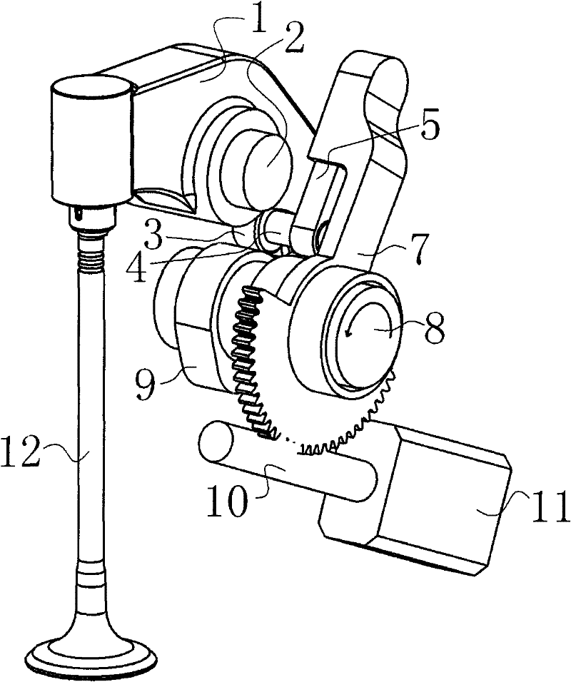
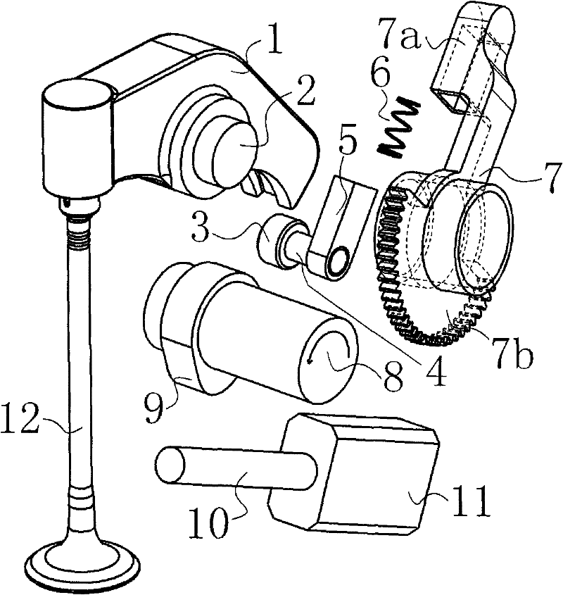
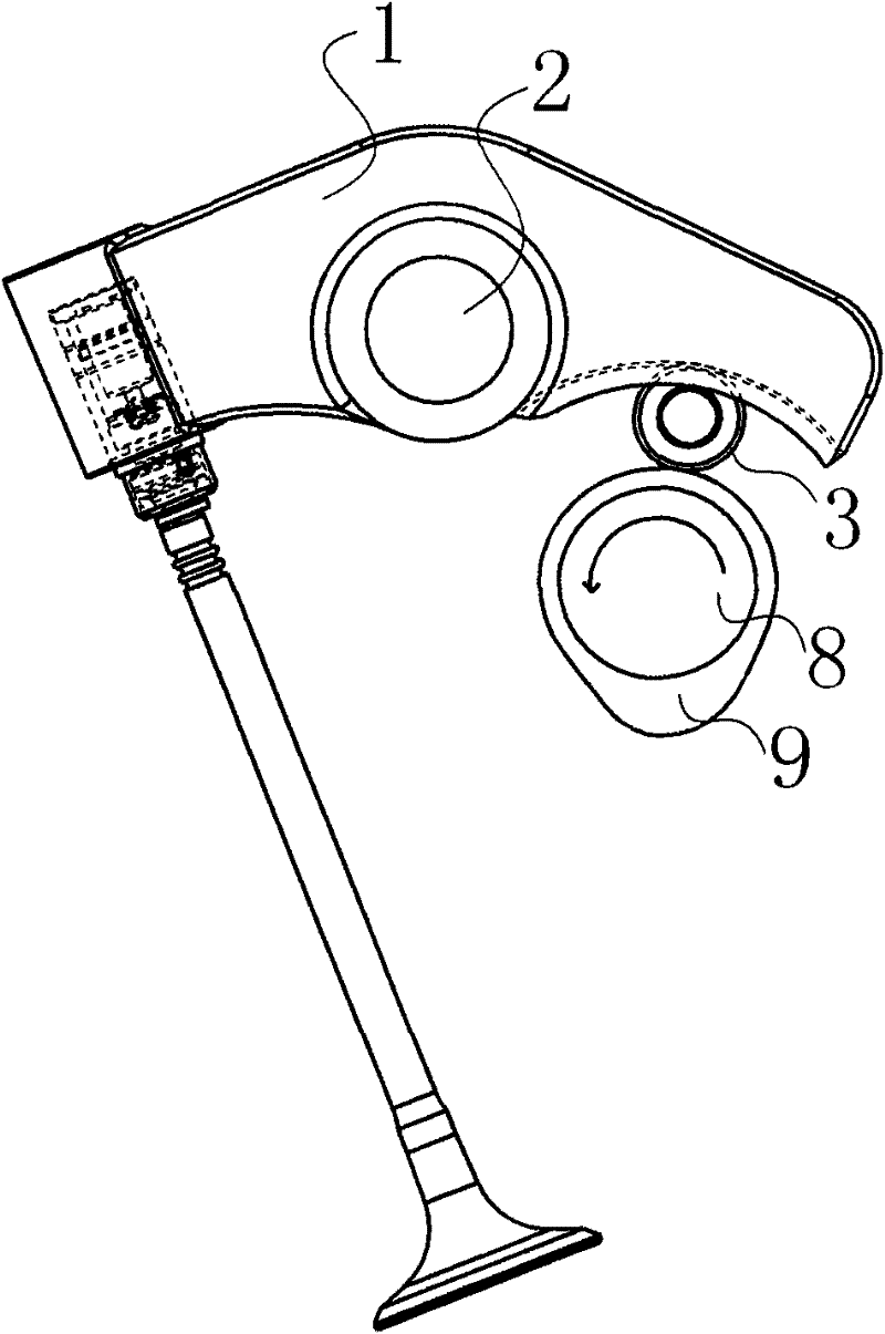
[0031] as attached figure 1 As shown, the present invention is a continuously variable valve lift device, including a rocker arm 1, a camshaft 8, a cam 9, and a valve 12. The continuously variable valve lift device also includes a rocker arm arc groove 1a , pivot 2, roller 3, pin 4, slide rod 5, control arm 7, worm 10, stepper motor 11, the rocker arm 1 is set on the pivot 2, the surface of roller 3 and rocker arm 1 Contact, the roller 3 is connected by the slide bar 5 of the pin shaft 4 connected to its surface, one end of the control arm 7 is a slideway 7a, the other end is a worm wheel 7b, the slide bar 5 is set wi...


PUM


Abstract

The invention provides a continuous variable valve lift device applied to a valve control system of an internal combustion engine, and also relates to a control method of the continuous variable valvelift device. A rocker (1) of the continuous variable valve lift device is sheathed on a pivot (2), a roller (3) is contacted with the surface of the rocker (1) and connected with a sliding rod (5) bya pin roll (4) connected with the surface of the roller (3); one end of a control arm (7) is provided with a slideway (7a), the other end thereof is provided with a worm gear (7b); and the sliding rod (5) is sheathed with the slideway (7a) with a hollow structure, the worm gear (7b) has the structure with cogs and is connected with a worm (10), and the worm (10) is controlled by a stepping motor(11). The technical proposal has simple and compact structure, easy realization, low cost and high reliability, and can change the lift characteristic of the valve, with better flexibility.

Description

technical field [0001] The invention relates to a valve control system of an internal combustion engine, more specifically, a continuously variable valve lift device for mechanically changing the valve lift, and a control method for the continuously variable valve lift device. Background technique [0002] The research on engine variable valve drive technology has a history of more than 100 years. Since the late 1980s, global energy and environmental issues have become increasingly prominent, and countries have increasingly stringent requirements for improving fuel economy and reducing harmful emissions, so a large number of variable valve drive mechanisms have emerged as the times require. The variable valve lift technology can make the engine obtain good performance in the whole speed and load range. Most of the patents in this field are from Japan and the United States, and there are more and more engine products applying this technology, but most of the variable valve l...

Claims


Application Information

Patent Timeline
Patent Type & Authority Patents(China)
IPC IPC(8): F02D13/02F01L13/00
CPCY02T10/18Y02T10/12
Inventor 胡耀华
Owner CHERY AUTOMOBILE CO LTD
Why Eureka
Try Eureka