
Driving device

A driving device and actuating mechanism technology, applied in the direction of valve devices, engine components, machines/engines, etc., can solve the problems of inaccurate adjustment, inability to adjust the opening and closing phase and stroke of intake and exhaust valves, and achieve small structural changes , Continuous adjustment of the valve switch phase and opening stroke, the effect of large adjustment ability

Active Publication Date: 2011-05-18
杨鲁川
View PDF3 Cites 7 Cited by
  • Summary
  • Abstract
  • Description
  • Claims
  • Application Information

AI Technical Summary

Problems solved by technology

But the shortcoming of this device is the same as the above-mentioned shortcoming in the prior art, all can not make bigger adjustment to the opening and closing phase and stroke of intake and exhaust valve, also can't it be adjusted accurately

Method used


Image

  • Driving device
  • Driving device
  • Driving device

Examples


Embodiment Construction

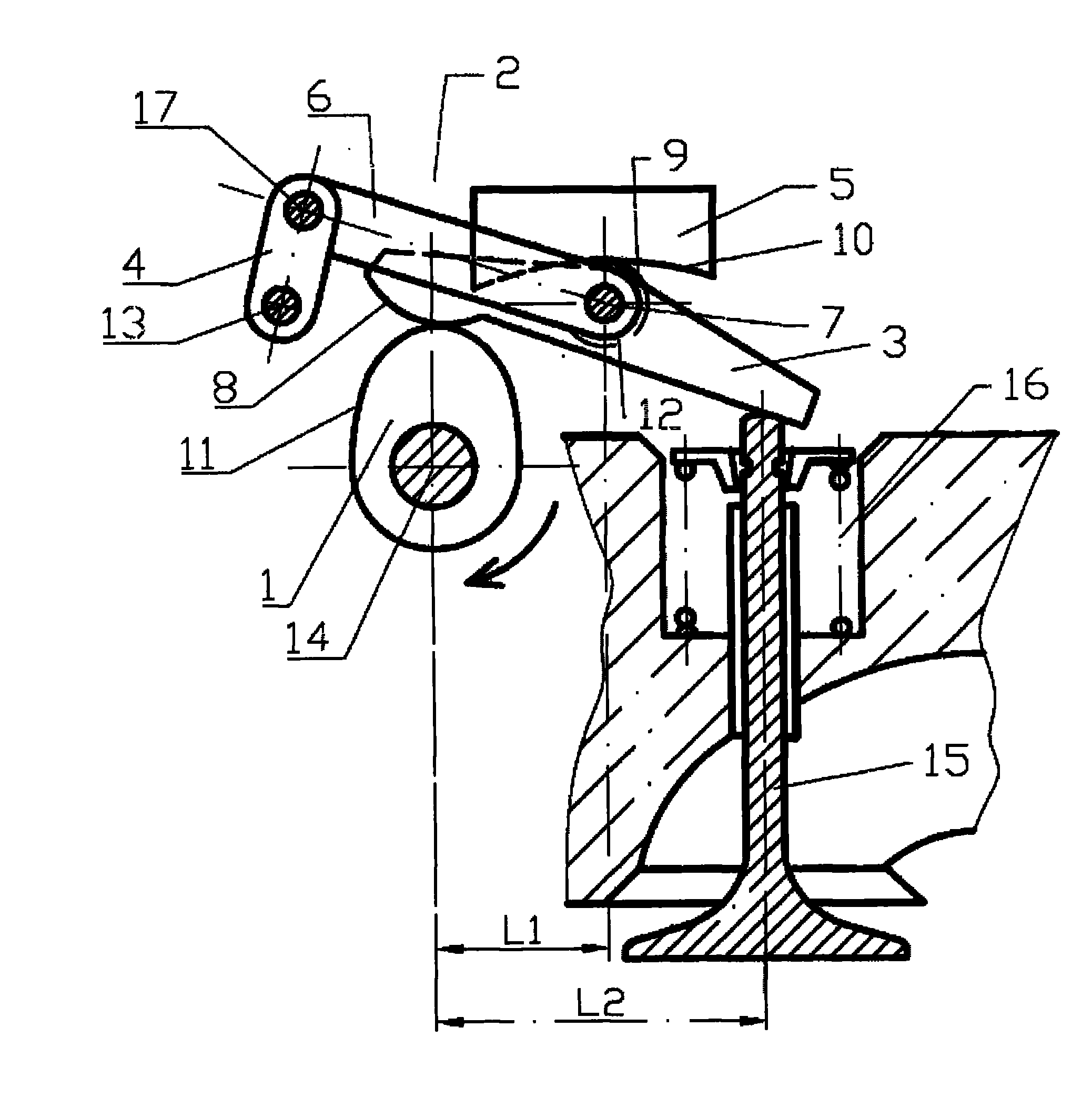
[0024] figure 1 An embodiment of the driving device according to the present invention is schematically shown. Such a drive device is particularly used to drive the movement of a valve stem of a cylinder of an internal combustion engine. In this embodiment, the internal combustion engine cylinder refers particularly to the internal combustion engine cylinder of a motorcycle. This cylinder is characterized by compact structure and small installation space.

[0025] Such as figure 1 As shown, in this embodiment, the driving device has a cam 1 which is mounted on the cam drive shaft 14. The cam drive shaft 14 is driven by another power device, thereby driving the cam 1 to rotate. The above-mentioned power plant is not shown in the figure.

[0026] Working with cam 1 is a rocker arm 3. In this embodiment, the rocker arm 3 is a strip-shaped plate-shaped member. The rocker arm 3 extends relatively long in the horizontal direction in the figure, and relatively narrow in the vertical ...


PUM


Abstract

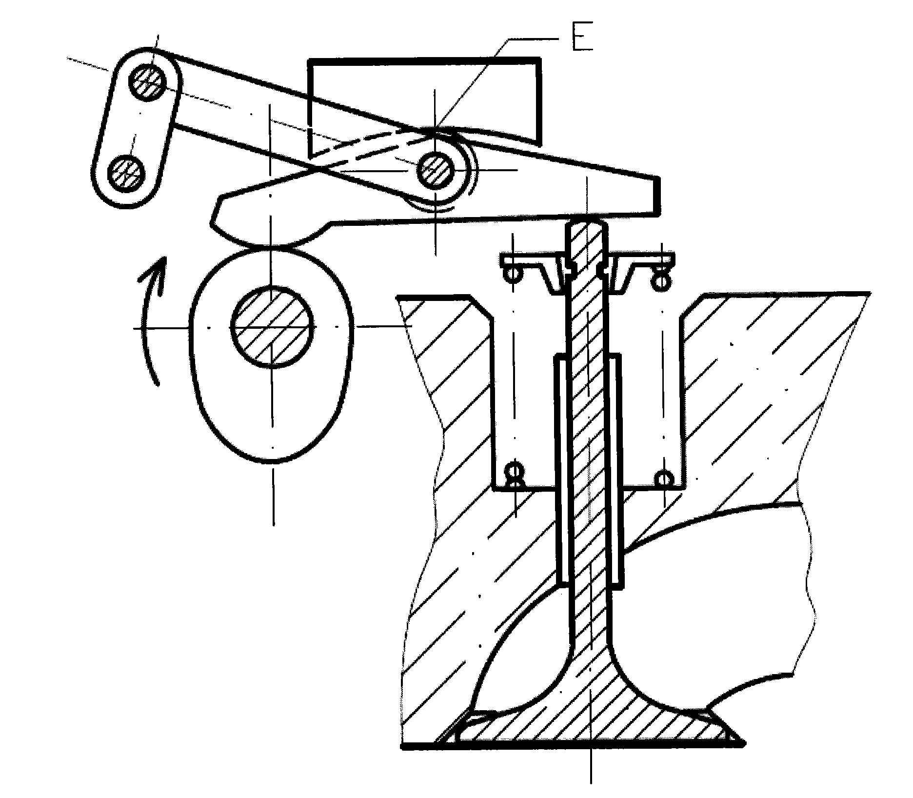
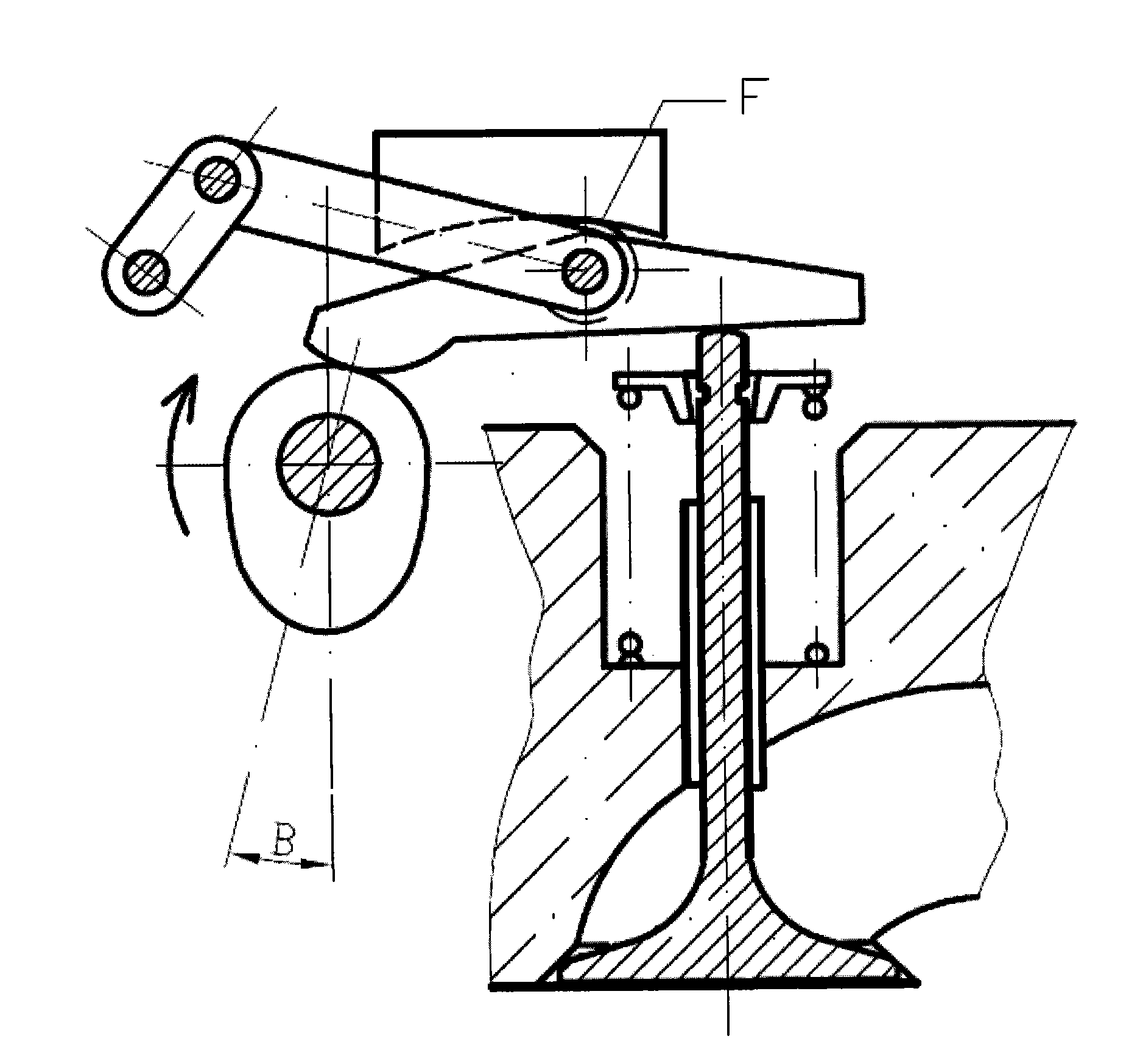
The invention provides a driving device. The driving device comprises a cam and a rocker arm, and also comprises an actuating mechanism, wherein the rocker arm is driven by the cam and is supported on a supporting shaft; the actuating mechanism is used for adjusting the position of the rocker arm and comprises at least one connecting rod, a crank and a guide supporting piece, wherein one end of the connecting rod is hinged with the middle part of the rocker arm through a supporting pin shaft; the other end of the connecting rod is hinged with the crank; the other end of the crank is hinged and supported to the supporting pin shaft; the guide supporting piece is provided with a work curved surface; and the part where the connecting rod and the rocker arm are hinged with each other is supported on the guide supporting piece movably. Because of increasing the adjustment of the opening stroke of a suction and exhaust valve of an air cylinder of an internal combustion engine by the actuating mechanism, the driving device has high capacity of adjusting the opening of the suction and exhaust valve. Because the stroke of the valve depends on the lift range of the cam and the structural parameter lever ratio (L2 / L1) of the rocker arm, so the characteristic of changing the lift range of the valve is achieved by adjusting cam lift range curve parameters and rocker arm structural parameters.

Description

Technical field [0001] The invention relates to a driving device, in particular to a driving device for opening and closing the intake and exhaust valves of an internal combustion engine, in particular to a driving device for opening and closing the intake and exhaust valves of the internal combustion engine of motorcycles and mini automobiles. Background technique [0002] European patent EP 1672183A1 discloses a rocker arm for forcibly controlling a valve device. Wherein, one end of the rocker arm is connected with an adjustment device, and a part of the adjustment device can extend outward to adjust the position of this end of the rocker arm. A rocker roller is arranged in the middle of the rocker arm, and the shaft of the roller is connected with the support shaft of the roller covered on the outer circumference of the cam through a connecting piece. However, the adjustment of the opening stroke of the valve by this forced control device is limited, that is, the stroke of th...

Claims


Application Information

Patent Timeline
Patent Type & Authority Applications(China)
IPC IPC(8): F01L13/00F01L1/18F01L1/30
CPCF01L13/0021F01L2105/00F01L1/182F01L2001/188F01L2305/00
Inventor 杨鲁川
Owner 杨鲁川
Learn More