
Metal evaporation crucible

A crucible and metal technology, applied in the field of vacuum thermal evaporation device, can solve problems such as heating wire 120 alloying, heating circuit short circuit, etc., and achieve the effect of reducing heating instability

Inactive Publication Date: 2011-05-25
INESA ELECTRON
View PDF0 Cites 12 Cited by
  • Summary
  • Abstract
  • Description
  • Claims
  • Application Information

AI Technical Summary

Problems solved by technology

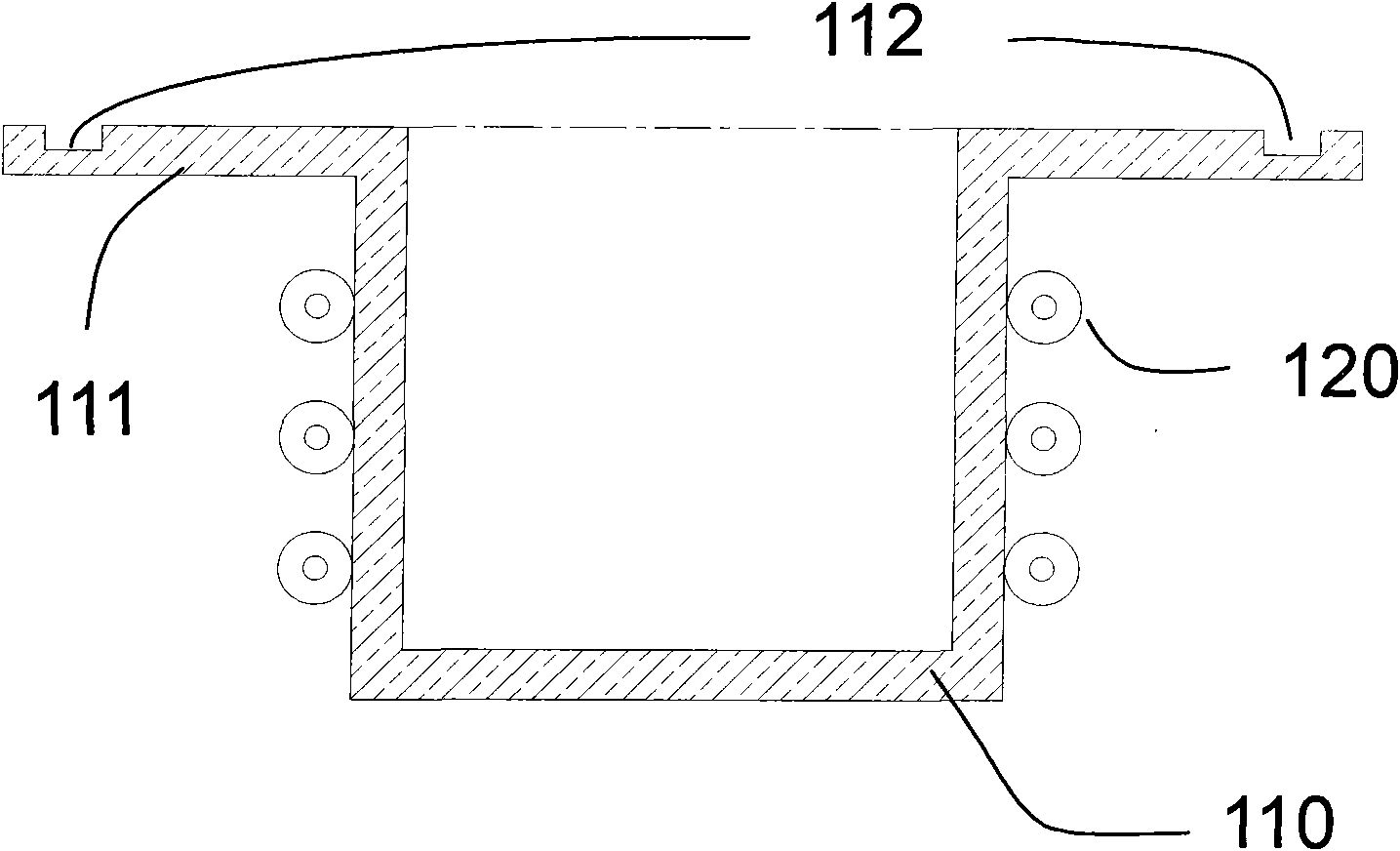
The crucible of this shape is prone to the problem that the heated molten metal will flow out along the inner wall and come into contact with the heating wire 120, causing alloying of the heating wire 120 or short circuit of the heating circuit

Method used


Image

  • Metal evaporation crucible
  • Metal evaporation crucible
  • Metal evaporation crucible

Examples


Embodiment 1

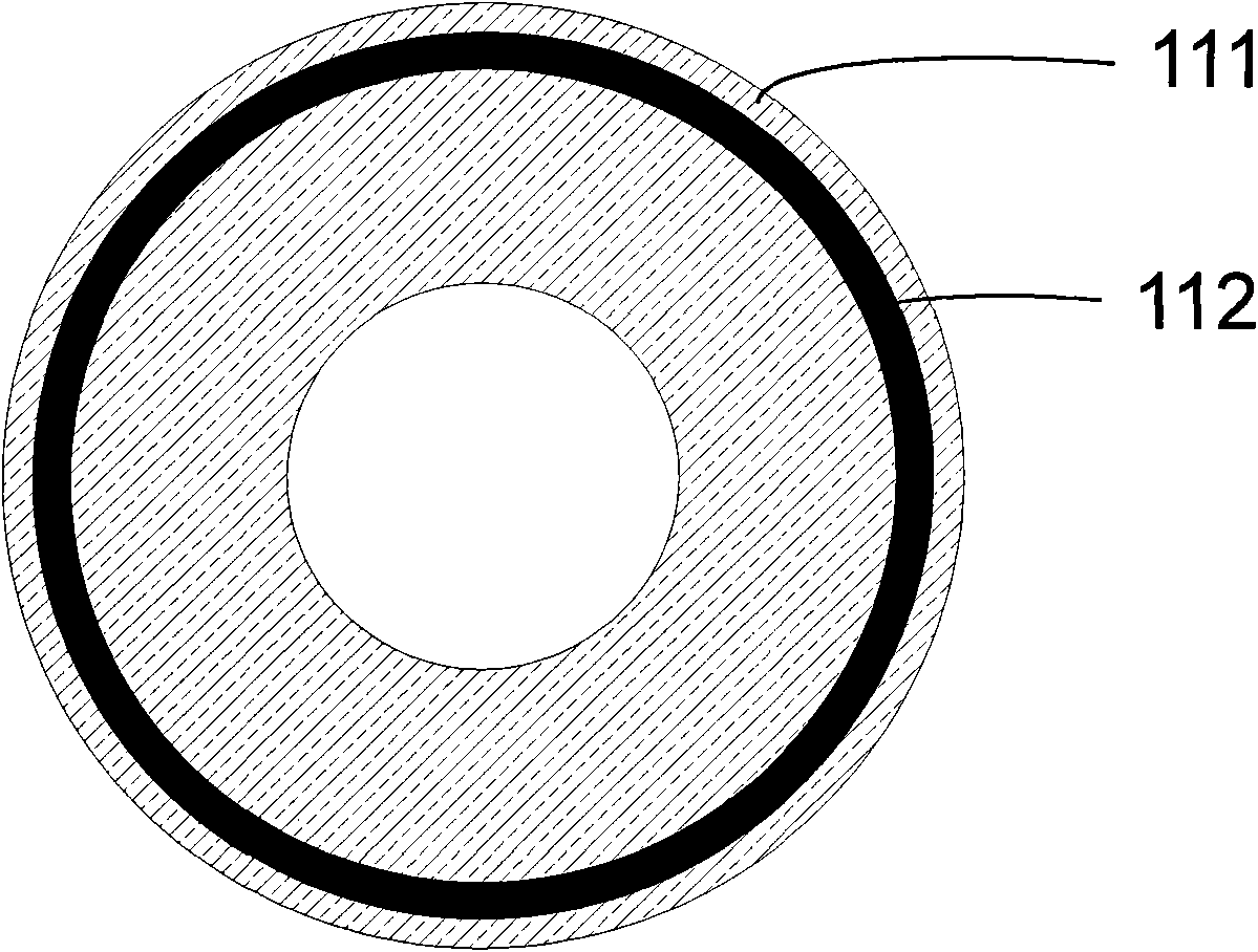
[0018] like figure 1 , as shown in 2, a crucible for evaporating metals includes a crucible container 110, an annular horizontal platform 111 and an annular flow-limiting groove 112 from the inside to the outside, and the crucible wall of the crucible container 110 extends horizontally at the mouth of the crucible, forming An annular horizontal platform 111, the width of the annular horizontal platform 111 is three times or more than the diameter of the heating wire 120, and the outer edge of the annular horizontal platform 111 inwardly does not exceed the width of an annular restricting groove 112 On the top, there is an annular current limiting groove 112, the depth of the annular current limiting groove 112 is about half of the thickness of the horizontal platform, and its width does not exceed the diameter of the heating wire 120. The crucible has a high thermal conductivity and high temperature resistance And it is made of non-metallic materials that do not chemically re...

Embodiment 2

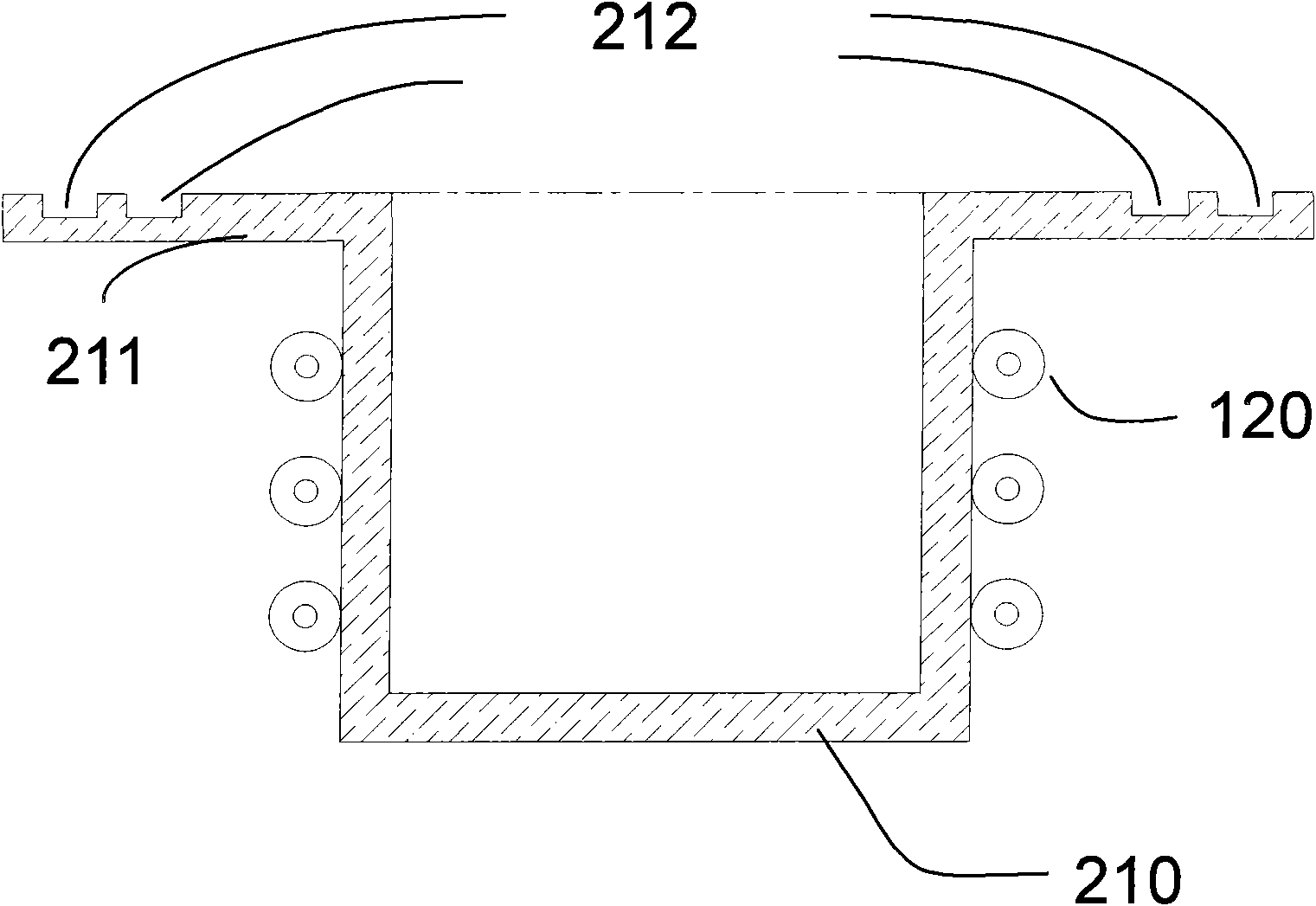
[0021] like image 3 , shown in 4, is another embodiment of the present invention. In this embodiment, the top of the heating body 210 is connected to an annular horizontal platform 211 perpendicular to the side of the main body. The annular horizontal platform 211 is close to the extension and has two flow-limiting grooves 212 distributed therein. Compared with Embodiment 1, the number of flow-limiting grooves is increased, so that when there is a large amount of molten metal overflowing and the overflow speed is too fast, it can effectively prevent the molten metal from flowing out of the platform and affect the vacuum cavity. Therefore, the vapor deposition process of the metal material plays a role of safety protection.

[0022] In the two embodiments of the present invention, the geometric dimensions of the crucible, the thickness of the crucible wall, the width of the horizontal platform and the depth of the restrictor groove are all determined by the shape of the heati...


PUM


Abstract

The invention relates to a metal evaporation crucible, which comprises a crucible container of which one end is open. The crucible is characterized in that: the open side of the crucible container is provided with an annular horizontal platform; the annular horizontal platform is provided with at least one annular current-limiting groove; the annular current-limiting groove is concentric with the annular horizontal platform and the crucible container and is positioned at the outer edge of the horizontal platform; the width of the annular horizontal platform is at least three times that of the cross section of a heater strip; the depth of the annular current-limiting groove is a half of the thickness of the annular horizontal platform; and the width of the annular current-limiting groove is smaller than the diameter of the heater strip. A relatively wide horizontal platform is provided, and the width of the horizontal platform is three or more times greater than the diameter of the cross section of the heater strip, so that metallic solution overflowing from the crucible body is prevented from contacting the heater strip hided below the horizontal platform after crossly surpassing the horizontal platform, and the situation of unstable heating caused by heating evaporation for the second time of the overflowing metallic solution is reduced.

Description

technical field [0001] The invention relates to a vacuum thermal evaporation device, in particular to a crucible for thermal evaporation of molten metal. Background technique [0002] Evaporation method is a vacuum coating technology belonging to physical vapor deposition. It puts the evaporated material in a crucible, and by heating the crucible, the material is converted from solid to gaseous atoms, atomic groups or molecules, and then condenses to the surface of the substrate to be coated to form a thin film. This technology is widely used in solar cells, semiconductor wafers, flat panel displays, optical lenses and other fields. [0003] At present, organic electroluminescent devices are attracting more and more attention as the core technology of the next generation flat panel display. The main method of device preparation is the evaporation method. Whether it is an organic functional layer, an organic light-emitting layer, or a metal electrode, it is evaporated by h...

Claims


Application Information

Patent Timeline
IPC IPC(8): C23C14/24C23C14/14
Inventor 李诺刘畅
Owner INESA ELECTRON
Learn More